1. What is RLC Circuit Calculator?
Definition: This calculator computes the impedance (\( Z \)), phase difference (\( \phi \)), quality factor (\( Q \)), resonant frequency (\( f_0 \)), angular frequency (\( \omega \)), and current (\( I \)) of an RLC circuit, which consists of a resistor (\( R \)), an inductor (\( L \)), and a capacitor (\( C \)) connected in series or parallel.
Purpose: It is used in electronics to analyze how an RLC circuit resists the flow of alternating current (AC) at a given frequency, its resonance characteristics, its quality, and the current flowing through it, which are essential for designing filters, oscillators, and impedance matching networks in RF applications.
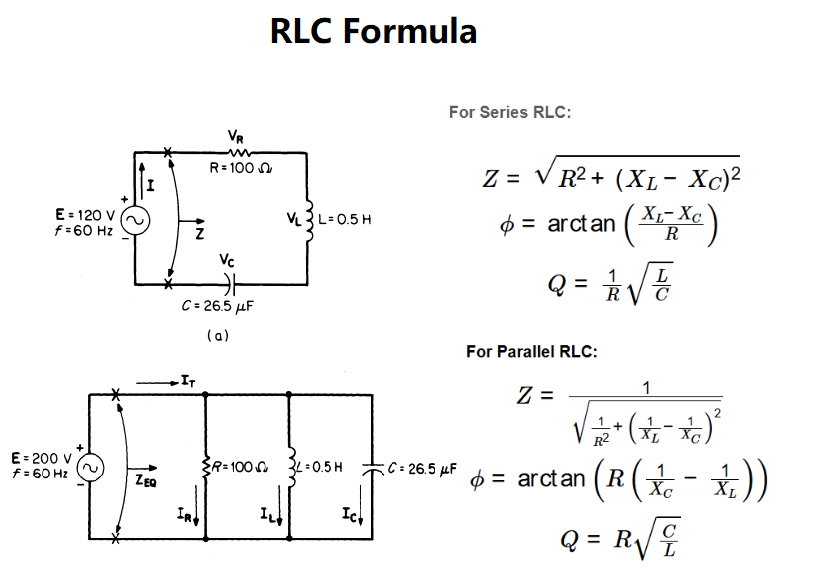
2. RLC Circuit Formula
The calculator uses the following formulas for an RLC circuit:
For Series RLC:
- \( Z = \sqrt{R^2 + (X_L - X_C)^2} \)
- \( \phi = \arctan\left(\frac{X_L - X_C}{R}\right) \)
- \( Q = \frac{1}{R} \sqrt{\frac{L}{C}} \)
- \( I = \frac{V}{Z} \)
For Parallel RLC:
- \( Z = \frac{1}{\sqrt{\frac{1}{R^2} + \left(\frac{1}{X_L} - \frac{1}{X_C}\right)^2}} \)
- \( \phi = \arctan\left(R \left(\frac{1}{X_C} - \frac{1}{X_L}\right)\right) \)
- \( Q = R \sqrt{\frac{C}{L}} \)
- \( I = \frac{V}{Z} \)
For Both Configurations:
- \( f_0 = \frac{1}{2 \pi \sqrt{L \times C}} \)
- \( \omega = 2 \pi f \)
- Where: \( X_L = \omega L \), \( X_C = \frac{1}{\omega C} \)
Where:
- \( Z \): Impedance magnitude (Ω);
- \( \phi \): Phase difference between voltage and current (degrees);
- \( Q \): Quality factor (unitless);
- \( f_0 \): Resonant frequency (Hz);
- \( \omega \): Angular frequency (rad/s);
- \( I \): Current (A);
- \( V \): Voltage (V);
- \( R \): Resistance (Ω);
- \( X_L \): Inductive reactance (Ω);
- \( X_C \): Capacitive reactance (Ω);
- \( L \): Inductance (H);
- \( C \): Capacitance (F);
- \( f \): Frequency (Hz).
Steps:
- Select the circuit type (series or parallel).
- Enter the resistance (\( R \)), inductance (\( L \)), capacitance (\( C \)), frequency (\( f \)), and voltage (\( V \)) with their units.
- Convert resistance to ohms, inductance to Henries, capacitance to Farads, frequency to Hertz, and voltage to Volts.
- Calculate the angular frequency using \( \omega = 2\pi f \).
- Calculate the resonant frequency using \( f_0 = \frac{1}{2 \pi \sqrt{L \times C}} \).
- Calculate the inductive reactance (\( X_L \)) and capacitive reactance (\( X_C \)).
- Calculate the impedance (\( Z \)), phase difference (\( \phi \)), and quality factor (\( Q \)) using the appropriate formulas for series or parallel configuration.
- Calculate the current using \( I = \frac{V}{Z} \).
- Convert the impedance, resonant frequency, angular frequency, and current to the selected output units.
- Display results in scientific notation if their absolute value is less than 0.001, otherwise with 4 decimal places.
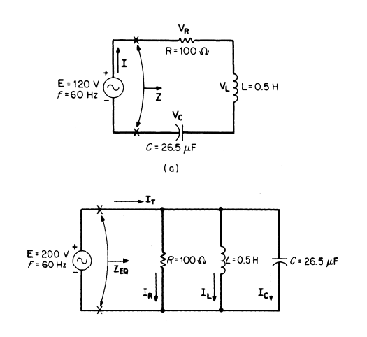
3. Series & Parallel RLC Circuit Diagram
4. Using the Calculator
Example 1 (Series RLC): Calculate the impedance, phase difference, Q-factor, resonant frequency, angular frequency, and current for a series RLC circuit with \( R = 100 \, \text{Ω} \), \( L = 1 \, \text{mH} \), \( C = 1 \, \text{nF} \), \( f = 10 \, \text{kHz} \), and \( V = 10 \, \text{V} \):
- Input Values:
- \( R = 100 \, \text{Ω} \);
- \( L = 1 \, \text{mH} = 1 \times 10^{-3} \, \text{H} \);
- \( C = 1 \, \text{nF} = 1 \times 10^{-9} \, \text{F} \);
- \( f = 10 \, \text{kHz} = 10 \times 10^3 \, \text{Hz} \);
- \( V = 10 \, \text{V} \);
- Angular Frequency: \( \omega = 2 \pi f = 2 \pi \times 10000 \approx 62831.85 \, \text{rad/s} \);
- Inductive Reactance: \( X_L = \omega L = 62831.85 \times 0.001 \approx 62.832 \, \text{Ω} \);
- Capacitive Reactance: \( X_C = \frac{1}{\omega C} = \frac{1}{62831.85 \times 10^{-9}} \approx 15915.49 \, \text{Ω} \);
- Impedance: \( Z = \sqrt{R^2 + (X_L - X_C)^2} = \sqrt{100^2 + (62.832 - 15915.49)^2} \approx 15853.02 \, \text{Ω} = 15.853 \, \text{kΩ} \);
- Phase Difference: \( \phi = \arctan\left(\frac{X_L - X_C}{R}\right) = \arctan\left(\frac{62.832 - 15915.49}{100}\right) \approx \arctan(-158.53) \approx -89.64^\circ \);
- Quality Factor: \( Q = \frac{1}{R} \sqrt{\frac{L}{C}} = \frac{1}{100} \sqrt{\frac{0.001}{10^{-9}}} \approx \frac{1}{100} \sqrt{10^6} = 10 \);
- Resonant Frequency: \( f_0 = \frac{1}{2 \pi \sqrt{L \times C}} = \frac{1}{2 \pi \sqrt{0.001 \times 10^{-9}}} \approx 159154.94 \, \text{Hz} = 159.155 \, \text{kHz} \);
- Current: \( I = \frac{V}{Z} = \frac{10}{15853.02} \approx 0.0006307 \, \text{A} = 0.6307 \, \text{mA} \);
- Result: \( Z = 15.8530 \, \text{kΩ} \), \( \phi = -89.6400^\circ \), \( Q = 10.0000 \), \( f_0 = 159.1549 \, \text{kHz} \), \( \omega = 6.2832e4 \, \text{rad/s} \), \( I = 0.6307 \, \text{mA} \).
Example 2 (Parallel RLC): Calculate the impedance, phase difference, Q-factor, resonant frequency, angular frequency, and current for a parallel RLC circuit with \( R = 1 \, \text{kΩ} \), \( L = 10 \, \text{mH} \), \( C = 100 \, \text{pF} \), \( f = 500 \, \text{kHz} \), and \( V = 5 \, \text{V} \):
- Input Values:
- \( R = 1 \, \text{kΩ} = 1000 \, \text{Ω} \);
- \( L = 10 \, \text{mH} = 10 \times 10^{-3} \, \text{H} \);
- \( C = 100 \, \text{pF} = 100 \times 10^{-12} \, \text{F} \);
- \( f = 500 \, \text{kHz} = 500 \times 10^3 \, \text{Hz} \);
- \( V = 5 \, \text{V} \);
- Angular Frequency: \( \omega = 2 \pi f = 2 \pi \times 500000 \approx 3141592.65 \, \text{rad/s} = 3.142 \, \text{Mrad/s} \);
- Inductive Reactance: \( X_L = \omega L = 3141592.65 \times 0.01 \approx 31415.93 \, \text{Ω} \);
- Capacitive Reactance: \( X_C = \frac{1}{\omega C} = \frac{1}{3141592.65 \times 10^{-10}} \approx 3183.10 \, \text{Ω} \);
- Impedance: \( Z = \frac{1}{\sqrt{\frac{1}{R^2} + \left(\frac{1}{X_L} - \frac{1}{X_C}\right)^2}} \), where \( \frac{1}{X_L} - \frac{1}{X_C} = \frac{1}{31415.93} - \frac{1}{3183.10} \approx -0.000282 \), so \( Z = \frac{1}{\sqrt{\left(\frac{1}{1000}\right)^2 + (-0.000282)^2}} \approx 3325.97 \, \text{Ω} \);
- Phase Difference: \( \phi = \arctan\left(R \left(\frac{1}{X_C} - \frac{1}{X_L}\right)\right) = \arctan(1000 \times (-0.000282)) \approx \arctan(-0.282) \approx -15.76^\circ \);
- Quality Factor: \( Q = R \sqrt{\frac{C}{L}} = 1000 \sqrt{\frac{10^{-10}}{0.01}} \approx 1000 \sqrt{10^{-8}} = 1000 \times 10^{-4} = 0.1 \);
- Resonant Frequency: \( f_0 = \frac{1}{2 \pi \sqrt{L \times C}} = \frac{1}{2 \pi \sqrt{0.01 \times 10^{-10}}} \approx 503292.48 \, \text{Hz} = 503.292 \, \text{kHz} \);
- Current: \( I = \frac{V}{Z} = \frac{5}{3325.97} \approx 0.001503 \, \text{A} = 1.503 \, \text{mA} \);
- Result: \( Z = 3325.9700 \, \text{Ω} \), \( \phi = -15.7600^\circ \), \( Q = 1.0000e-1 \), \( f_0 = 503.2925 \, \text{kHz} \), \( \omega = 3.1416 \, \text{Mrad/s} \), \( I = 1.5030 \, \text{mA} \).
5. Frequently Asked Questions (FAQ)
Q: What does the Q-factor indicate in an RLC circuit?
A: The Q-factor measures the quality of resonance in the circuit. A higher Q-factor indicates sharper resonance (narrower bandwidth) and longer-lasting oscillations, while a low Q-factor (e.g., less than 0.5) means the oscillations die out quickly.
Q: Why does impedance vary with frequency in RLC circuits?
A: Impedance varies because the inductive reactance (\( X_L \)) increases with frequency (\( X_L = \omega L \)), while the capacitive reactance (\( X_C \)) decreases with frequency (\( X_C = \frac{1}{\omega C} \)). This frequency dependence affects the total impedance.
Q: How does the circuit type affect impedance calculations?
A: In a series RLC circuit, impedance is the vector sum of resistance and reactances, often resulting in a larger value. In a parallel RLC circuit, the reciprocal of impedance combines the reciprocals of resistance and reactances, often resulting in a smaller impedance at resonance.
Q: Why is the current calculated in the RLC circuit?
A: The current (\( I = \frac{V}{Z} \)) is calculated to determine the flow of AC current through the circuit, which is critical for assessing power consumption, component ratings, and circuit performance.
 Home
Home
 Back
Back