1. What is a Wilkinson Power Divider Calculator?
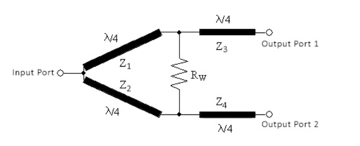
Definition: This calculator computes the impedances (\( Z_1, Z_2, Z_3, Z_4 \)) and the resistor (\( R_W \)) for an unequal Wilkinson power divider, which splits input power between two output ports with a specified ratio (\( P_A / P_B \)).
Purpose: It assists RF engineers in designing Wilkinson power dividers for applications requiring unequal power splitting, such as in antenna arrays, RF amplifiers, and communication systems, ensuring proper impedance matching and isolation.
2. How Does the Calculator Work?
The calculator uses the following formulas to compute the impedances and resistor:
Impedance \( Z_1 \) in Ohms:
\[
Z_1 = Z_0 \times \left( \left( \frac{P_A}{P_B} \right)^{-1.5} + \left( \frac{P_A}{P_B} \right)^{-0.5} \right)^{0.5}
\]
Impedance \( Z_2 \) in Ohms:
\[
Z_2 = Z_0 \times \left( 1 + \frac{P_A}{P_B} \right)^{0.5} \times \left( \frac{P_A}{P_B} \right)^{0.25}
\]
Impedance \( Z_3 \) in Ohms:
\[
Z_3 = Z_0 \left( \frac{P_A}{P_B} \right)^{-0.25}
\]
Impedance \( Z_4 \) in Ohms:
\[
Z_4 = Z_0 \left( \frac{P_A}{P_B} \right)^{0.25}
\]
Resistor \( R_W \) in Ohms:
\[
R_W = Z_0 \left( \left( \frac{P_A}{P_B} \right)^{0.5} + \left( \frac{P_A}{P_B} \right)^{-0.5} \right)
\]
Where:
- \( Z_0 \): Characteristic impedance (typically 50 ohms)
- \( P_A \): Power at Port A
- \( P_B \): Power at Port B
Steps:
- Enter the characteristic impedance \( Z_0 \) in ohms (e.g., 50 ohms).
- Enter the power at Port A (\( P_A \)) and Port B (\( P_B \)), which define the power split ratio.
- Click "Calculate" to compute \( Z_1, Z_2, Z_3, Z_4, \) and \( R_W \).
- Results are displayed in ohms.
3. Importance of Wilkinson Power Divider Calculations
Calculating Wilkinson power divider parameters is essential for:
- Unequal Power Splitting: Enables precise power distribution between two ports, useful in applications like feeding different antenna elements with specific power levels.
- Impedance Matching: Ensures proper matching to avoid signal reflections and maximize power transfer.
- Isolation: The resistor \( R_W \) provides isolation between output ports, reducing interference in RF systems.
4. Using the Calculator
Examples:
- Example 1: Equal Split \( Z_0 = 50 \, \text{ohms}, P_A = 1, P_B = 1 \)
- Ratio \( \frac{P_A}{P_B} = 1 \)
- \( Z_1 = 50 \times \left( 1^{-1.5} + 1^{-0.5} \right)^{0.5} = 50 \times \left( 1 + 1 \right)^{0.5} = 50 \times \sqrt{2} \approx 70.71 \, \text{ohms} \)
- \( Z_2 = 50 \times \left( 1 + 1 \right)^{0.5} \times 1^{0.25} = 50 \times \sqrt{2} \times 1 \approx 70.71 \, \text{ohms} \)
- \( Z_3 = 50 \times 1^{-0.25} = 50 \times 1 = 50 \, \text{ohms} \)
- \( Z_4 = 50 \times 1^{0.25} = 50 \times 1 = 50 \, \text{ohms} \)
- \( R_W = 50 \left( 1^{0.5} + 1^{-0.5} \right) = 50 \left( 1 + 1 \right) = 100 \, \text{ohms} \)
- Example 2: Unequal Split \( Z_0 = 50 \, \text{ohms}, P_A = 3, P_B = 1 \)
- Ratio \( \frac{P_A}{P_B} = 3 \)
- \( Z_1 = 50 \times \left( 3^{-1.5} + 3^{-0.5} \right)^{0.5} \approx 50 \times \left( 0.192 + 0.577 \right)^{0.5} \approx 50 \times \sqrt{0.769} \approx 43.89 \, \text{ohms} \)
- \( Z_2 = 50 \times \left( 1 + 3 \right)^{0.5} \times 3^{0.25} \approx 50 \times \sqrt{4} \times 1.316 \approx 50 \times 2 \times 1.316 \approx 131.60 \, \text{ohms} \)
- \( Z_3 = 50 \times 3^{-0.25} \approx 50 \times 0.759 \approx 37.97 \, \text{ohms} \)
- \( Z_4 = 50 \times 3^{0.25} \approx 50 \times 1.316 \approx 65.82 \, \text{ohms} \)
- \( R_W = 50 \left( 3^{0.5} + 3^{-0.5} \right) \approx 50 \left( 1.732 + 0.577 \right) \approx 115.47 \, \text{ohms} \)
- Example 3: Unequal Split \( Z_0 = 50 \, \text{ohms}, P_A = 1, P_B = 2 \)
- Ratio \( \frac{P_A}{P_B} = 0.5 \)
- \( Z_1 = 50 \times \left( 0.5^{-1.5} + 0.5^{-0.5} \right)^{0.5} \approx 50 \times \left( 2.828 + 1.414 \right)^{0.5} \approx 50 \times \sqrt{4.242} \approx 103.00 \, \text{ohms} \)
- \( Z_2 = 50 \times \left( 1 + 0.5 \right)^{0.5} \times 0.5^{0.25} \approx 50 \times \sqrt{1.5} \times 0.841 \approx 50 \times 1.224 \times 0.841 \approx 51.52 \, \text{ohms} \)
- \( Z_3 = 50 \times 0.5^{-0.25} \approx 50 \times 1.189 \approx 59.47 \, \text{ohms} \)
- \( Z_4 = 50 \times 0.5^{0.25} \approx 50 \times 0.841 \approx 42.05 \, \text{ohms} \)
- \( R_W = 50 \left( 0.5^{0.5} + 0.5^{-0.5} \right) \approx 50 \left( 0.707 + 1.414 \right) \approx 106.07 \, \text{ohms} \)
5. Frequently Asked Questions (FAQ)
Q: What is a Wilkinson power divider?
A: A Wilkinson power divider is an RF component that splits an input signal into two output signals with a specified power ratio, while providing impedance matching and isolation between the output ports. It’s commonly used in RF systems for signal distribution.
Q: Why use an unequal Wilkinson power divider?
A: An unequal Wilkinson power divider is used when different power levels are needed at the output ports, such as in antenna arrays where one element requires more power than another for beamforming or coverage purposes.
Q: What is the role of the resistor \( R_W \)?
A: The resistor \( R_W \) provides isolation between the two output ports, reducing interference and ensuring that signals reflected from one port do not affect the other.
Wilkinson Power Divider Calculator© - All Rights Reserved 2025
 Home
Home
 Back
Back