1. What is a Varactor Diode?
Definition: A varactor diode, also known as a varicap diode, is a type of diode whose capacitance varies with the applied reverse bias voltage. It is used as a voltage-controlled capacitor in RF circuits.
Purpose: This calculator determines the junction capacitance, resonant frequency, and quality factor of a varactor diode, which are essential for designing tunable RF circuits like oscillators and filters.
2. How Does the Calculator Work?
The calculator uses the following formulas for varactor diode parameters:
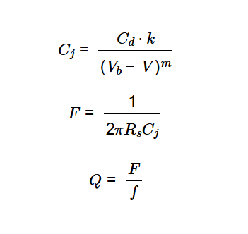
Varactor Capacitance (\( C_j \)):
\[
C_j = \frac{C_d \cdot k}{(V_b - V)^m}
\]
Resonant Frequency (\( F \)):
\[
F = \frac{1}{2 \pi R_s C_j}
\]
Quality Factor (\( Q \)):
\[
Q = \frac{F}{f}
\]
Where:
- \( C_j \): Junction capacitance (converted to F or pF)
- \( C_d \): Capacitance at zero bias (converted to farads from F or pF)
- \( k \): Constant factor (unitless, default 1)
- \( V_b \): Built-in potential (in volts, V)
- \( V \): Applied reverse bias voltage (in volts, V)
- \( m \): Junction grading coefficient (unitless, default 0.5)
- \( F \): Resonant frequency (converted to Hz, kHz, MHz, or GHz)
- \( R_s \): Series resistance (in ohms, \( \Omega \))
- \( Q \): Quality factor (unitless)
- \( f \): Operating frequency (converted to Hz from Hz, kHz, MHz, or GHz)
Steps:
- Enter the zero-bias capacitance \( C_d \), constant factor \( k \), built-in potential \( V_b \), applied voltage \( V \), junction grading coefficient \( m \), series resistance \( R_s \), and operating frequency \( f \), selecting appropriate units.
- Click "Calculate" to compute the varactor capacitance, resonant frequency, and quality factor.
- Select the output units for \( C_j \) (F, pF) and \( F \) (Hz, kHz, MHz, GHz) in the result section.
- Results are displayed with 4 decimal places, or in scientific notation if less than 0.001.
3. Importance of Varactor Diode Calculations
Varactor diode calculations are essential for:
- Tunable Circuits: Enables the design of voltage-controlled oscillators (VCOs) and filters in RF applications.
- Frequency Modulation: Supports frequency modulation and tuning in communication systems.
- Performance Optimization: Determines the quality factor to assess the efficiency of the varactor in resonant circuits.
4. Using the Calculator
Examples:
- Example 1: Typical Varactor at 1 GHz (Capacitance in pF, Frequency in GHz)
- \( C_d = 10 \, \text{pF} \), \( k = 1 \), \( V_b = 0.7 \, \text{V} \), \( V = 0 \, \text{V} \), \( m = 0.5 \), \( R_s = 1 \, \Omega \), \( f = 1 \, \text{GHz} \)
- \( C_j = \frac{10 \times 10^{-12} \times 1}{(0.7 - 0)^{0.5}} \approx 1.1952 \times 10^{-11} \, \text{F} \), in pF: \( 11.9523 \)
- \( F = \frac{1}{2 \pi \times 1 \times 1.1952 \times 10^{-11}} \approx 1.3316 \times 10^{10} \, \text{Hz} \), in GHz: \( 13.3165 \)
- \( Q = \frac{1.3316 \times 10^{10}}{1 \times 10^9} = 13.3165 \)
- Example 2: Varactor with Bias at 100 MHz (Capacitance in pF, Frequency in MHz)
- \( C_d = 20 \, \text{pF} \), \( k = 1 \), \( V_b = 0.9 \, \text{V} \), \( V = 0.2 \, \text{V} \), \( m = 0.5 \), \( R_s = 0.5 \, \Omega \), \( f = 100 \, \text{MHz} \)
- \( C_j = \frac{20 \times 10^{-12} \times 1}{(0.9 - 0.2)^{0.5}} \approx 2.3905 \times 10^{-11} \, \text{F} \), in pF: \( 23.9045 \)
- \( F = \frac{1}{2 \pi \times 0.5 \times 2.3905 \times 10^{-11}} \approx 1.3316 \times 10^{10} \, \text{Hz} \), in MHz: \( 13316.4972 \)
- \( Q = \frac{1.3316 \times 10^{10}}{100 \times 10^6} = 133.1650 \)
- Example 3: Custom Parameters at 1 MHz (Capacitance in F, Frequency in MHz)
- \( C_d = 5 \, \text{pF} \), \( k = 0.9 \), \( V_b = 1 \, \text{V} \), \( V = 0.1 \, \text{V} \), \( m = 0.33 \), \( R_s = 2 \, \Omega \), \( f = 1 \, \text{MHz} \)
- \( C_j = \frac{5 \times 10^{-12} \times 0.9}{(1 - 0.1)^{0.33}} \approx 4.6287 \times 10^{-12} \, \text{F} \)
- \( F = \frac{1}{2 \pi \times 2 \times 4.6287 \times 10^{-12}} \approx 1.7183 \times 10^{10} \, \text{Hz} \), in MHz: \( 17182.5035 \)
- \( Q = \frac{1.7183 \times 10^{10}}{1 \times 10^6} = 17182.5035 \)
5. Frequently Asked Questions (FAQ)
Q: What is a varactor diode used for?
A: Varactor diodes are used in RF circuits for tuning purposes, such as in voltage-controlled oscillators (VCOs), phase-locked loops (PLLs), and tunable filters.
Q: Why does capacitance decrease with reverse bias voltage?
A: As the reverse bias voltage (\( V \)) increases, the depletion region in the diode widens, reducing the effective capacitance (\( C_j \)) according to the formula \( C_j \propto (V_b - V)^{-m} \).
Q: What is the quality factor of a varactor diode?
A: The quality factor (\( Q \)) measures the efficiency of the varactor in a resonant circuit, defined as the ratio of the resonant frequency to the operating frequency.
Varactor Diode Calculator© - All Rights Reserved 2025
 Home
Home
 Back
Back