1. What is RLC Circuit Calculator?
Definition: This calculator computes the resonant frequency (\( f \)) and Q-factor (\( Q \)) of a series RLC circuit, which consists of a resistor (\( R \)), an inductor (\( L \)), and a capacitor (\( C \)) connected in series.
Purpose: It is used in electronics to determine the natural frequency at which an RLC circuit oscillates and the quality of its resonance, which are essential for designing filters, oscillators, and tuning circuits in radios and other RF applications.
2. How Does the Calculator Work?
The calculator uses the following formulas for a series RLC circuit:
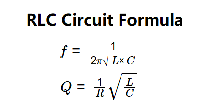
- \( f = \frac{1}{2 \pi \sqrt{L \times C}} \)
- \( Q = \frac{1}{R} \sqrt{\frac{L}{C}} \)
Where:
- \( f \): Resonant frequency (Hz);
- \( Q \): Q-factor (unitless);
- \( R \): Resistance (Ω);
- \( L \): Inductance (H);
- \( C \): Capacitance (F).
Steps:
- Enter the resistance (\( R \)), inductance (\( L \)), and capacitance (\( C \)) with their units.
- Convert resistance to ohms, inductance to Henries, and capacitance to Farads.
- Calculate the resonant frequency using the formula above.
- Calculate the Q-factor using the formula above.
- Convert the frequency to the selected output unit (Hz/kHz/MHz).
- Display results in scientific notation if their absolute value is less than 0.001, otherwise with 4 decimal places.
3. Importance of RLC Circuit Calculation
Calculating the resonant frequency and Q-factor of an RLC circuit is crucial for:
- Signal Processing: Designing bandpass filters and oscillators used in radios, amplifiers, and tuners to select specific frequencies.
- RF Applications: Tuning circuits in transmitters and receivers to match the frequency of incoming signals, ensuring clear communication.
- Circuit Design: Ensuring that RLC circuits operate at their natural frequency with optimal quality for maximum efficiency and performance.
4. Using the Calculator
Example 1: Calculate the resonant frequency and Q-factor for an RLC circuit with \( R = 1 \, \text{kΩ} \), \( L = 1 \, \text{mH} \), and \( C = 2 \, \text{pF} \):
- Input Values:
- \( R = 1 \, \text{kΩ} = 1000 \, \text{Ω} \);
- \( L = 1 \, \text{mH} = 1 \times 10^{-3} \, \text{H} \);
- \( C = 2 \, \text{pF} = 2 \times 10^{-12} \, \text{F} \);
- LC Product: \( L \times C = (1 \times 10^{-3}) \times (2 \times 10^{-12}) = 2 \times 10^{-15} \);
- Resonant Frequency: \( f = \frac{1}{2 \pi \sqrt{L \times C}} = \frac{1}{2 \pi \sqrt{2 \times 10^{-15}}} \approx 112540 \, \text{Hz} = 112.540 \, \text{kHz} \);
- Q-Factor: \( Q = \frac{1}{R} \sqrt{\frac{L}{C}} = \frac{1}{1000} \sqrt{\frac{1 \times 10^{-3}}{2 \times 10^{-12}}} = \frac{1}{1000} \sqrt{5 \times 10^8} \approx 0.707 \);
- Result: \( f = 112.5400 \, \text{kHz} \), \( Q = 7.0711e-1 \).
Example 2: Calculate the resonant frequency and Q-factor for an RLC circuit with \( R = 10 \, \text{Ω} \), \( L = 5 \, \text{mH} \), and \( C = 100 \, \text{nF} \):
- Input Values:
- \( R = 10 \, \text{Ω} \);
- \( L = 5 \, \text{mH} = 5 \times 10^{-3} \, \text{H} \);
- \( C = 100 \, \text{nF} = 100 \times 10^{-9} = 1 \times 10^{-7} \, \text{F} \);
- LC Product: \( L \times C = (5 \times 10^{-3}) \times (1 \times 10^{-7}) = 5 \times 10^{-10} \);
- Resonant Frequency: \( f = \frac{1}{2 \pi \sqrt{L \times C}} = \frac{1}{2 \pi \sqrt{5 \times 10^{-10}}} \approx 7117.91 \, \text{Hz} \);
- Q-Factor: \( Q = \frac{1}{R} \sqrt{\frac{L}{C}} = \frac{1}{10} \sqrt{\frac{5 \times 10^{-3}}{1 \times 10^{-7}}} = \frac{1}{10} \sqrt{50000} \approx 22.361 \);
- Result: \( f = 7117.9100 \, \text{Hz} \), \( Q = 22.3610 \).
5. Frequently Asked Questions (FAQ)
Q: What does the Q-factor indicate in an RLC circuit?
A: The Q-factor measures the quality of resonance in the circuit. A higher Q-factor indicates sharper resonance (narrower bandwidth) and longer-lasting oscillations, while a Q-factor less than 0.5 means the oscillations die out quickly.
Q: Why is the resonant frequency important in RLC circuits?
A: The resonant frequency is the natural frequency at which the RLC circuit oscillates with maximum current amplitude, making it critical for applications like tuning radios, where the circuit must select a specific frequency from a complex signal.
Q: Does this calculator account for parallel RLC circuits?
A: No, this calculator is designed for series RLC circuits. In parallel RLC circuits, the resonant frequency formula is the same, but the Q-factor calculation differs due to the different configuration of components.
 Home
Home
 Back
Back