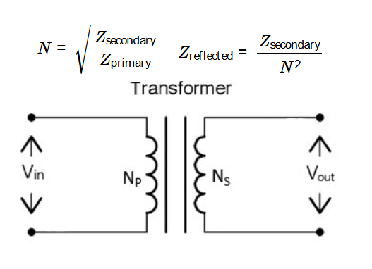
1. What is an RF Transformer?
Definition: An RF transformer is a device used in radio frequency circuits to transfer energy between two circuits while transforming impedance levels. It typically consists of two or more windings with a specific turns ratio.
Purpose: This calculator determines key parameters of an RF transformer, including the turns ratio, reflected impedance, and inductance values, which are essential for impedance matching in RF circuits such as antennas, amplifiers, and mixers.
2. How Does the Calculator Work?
The calculator uses the following formulas for RF transformer parameters:
Turns Ratio (\( N \)):
\[
N = \sqrt{\frac{Z_{\text{secondary}}}{Z_{\text{primary}}}}
\]
Reflected Impedance (\( Z_{\text{reflected}} \)):
\[
Z_{\text{reflected}} = \frac{Z_{\text{secondary}}}{N^2}
\]
Primary Inductance (\( L_{\text{primary}} \)):
\[
L_{\text{primary}} = \frac{Z_{\text{primary}}}{2 \pi f}
\]
Secondary Inductance (\( L_{\text{secondary}} \)):
\[
L_{\text{secondary}} = L_{\text{primary}} \times N^2
\]
Where:
- \( N \): Turns ratio (unitless)
- \( Z_{\text{primary}} \): Primary impedance (in ohms, \( \Omega \))
- \( Z_{\text{secondary}} \): Secondary impedance (in ohms, \( \Omega \))
- \( Z_{\text{reflected}} \): Reflected impedance (in ohms, \( \Omega \))
- \( L_{\text{primary}} \): Primary inductance (converted to H, mH, or µH)
- \( L_{\text{secondary}} \): Secondary inductance (converted to H, mH, or µH)
- \( f \): Operating frequency (converted to Hz from Hz, kHz, MHz, or GHz)
Steps:
- Enter the primary impedance \( Z_{\text{primary}} \), secondary impedance \( Z_{\text{secondary}} \), and operating frequency \( f \), selecting the frequency unit.
- Click "Calculate" to compute the turns ratio, reflected impedance, primary inductance, and secondary inductance.
- Select the output unit for inductances (\( L_{\text{primary}} \), \( L_{\text{secondary}} \)) (H, mH, µH) in the result section.
- Results are displayed with 4 decimal places, or in scientific notation if less than 0.001.
3. Importance of RF Transformer Calculations
RF transformer calculations are crucial for:
- Impedance Matching: Ensures maximum power transfer between RF circuit components like antennas and amplifiers.
- Circuit Design: Determines the inductance values needed for transformer windings at specific frequencies.
- Signal Integrity: Reduces reflections by matching impedances, improving performance in high-frequency applications.
4. Using the Calculator
Examples:
- Example 1: Typical RF Matching (Inductances in µH)
- \( Z_{\text{primary}} = 50 \, \Omega, Z_{\text{secondary}} = 200 \, \Omega, f = 100 \, \text{MHz} \)
- Convert: \( f = 100 \times 10^6 \, \text{Hz} \)
- Turns Ratio: \( N = \sqrt{\frac{200}{50}} = 2.0000 \)
- Reflected Impedance: \( Z_{\text{reflected}} = \frac{200}{2^2} = 50.0000 \, \Omega \)
- Primary Inductance: \( L_{\text{primary}} = \frac{50}{2 \pi \times 100 \times 10^6} \approx 7.96 \times 10^{-8} \, \text{H} \), in µH: \( 0.0796 \)
- Secondary Inductance: \( L_{\text{secondary}} = 7.96 \times 10^{-8} \times 2^2 \approx 3.18 \times 10^{-7} \, \text{H} \), in µH: \( 0.3185 \)
- Example 2: High Frequency (Inductances in mH)
- \( Z_{\text{primary}} = 100 \, \Omega, Z_{\text{secondary}} = 25 \, \Omega, f = 1 \, \text{GHz} \)
- Convert: \( f = 1 \times 10^9 \, \text{Hz} \)
- Turns Ratio: \( N = \sqrt{\frac{25}{100}} = 0.5000 \)
- Reflected Impedance: \( Z_{\text{reflected}} = \frac{25}{0.5^2} = 100.0000 \, \Omega \)
- Primary Inductance: \( L_{\text{primary}} = \frac{100}{2 \pi \times 1 \times 10^9} \approx 1.59 \times 10^{-8} \, \text{H} \), in mH: \( 1.5915 \times 10^{-5} \)
- Secondary Inductance: \( L_{\text{secondary}} = 1.59 \times 10^{-8} \times 0.5^2 \approx 3.98 \times 10^{-9} \, \text{H} \), in mH: \( 3.9789 \times 10^{-6} \)
- Example 3: Low Frequency (Inductances in H)
- \( Z_{\text{primary}} = 75 \, \Omega, Z_{\text{secondary}} = 300 \, \Omega, f = 1 \, \text{MHz} \)
- Convert: \( f = 1 \times 10^6 \, \text{Hz} \)
- Turns Ratio: \( N = \sqrt{\frac{300}{75}} = 2.0000 \)
- Reflected Impedance: \( Z_{\text{reflected}} = \frac{300}{2^2} = 75.0000 \, \Omega \)
- Primary Inductance: \( L_{\text{primary}} = \frac{75}{2 \pi \times 1 \times 10^6} \approx 1.19 \times 10^{-5} \, \text{H} \approx 0.0000 \)
- Secondary Inductance: \( L_{\text{secondary}} = 1.19 \times 10^{-5} \times 2^2 \approx 4.77 \times 10^{-5} \, \text{H} \approx 0.0000 \)
5. Frequently Asked Questions (FAQ)
Q: What is the turns ratio in an RF transformer?
A: The turns ratio (\( N \)) is the ratio of the number of turns in the primary winding to the secondary winding, determining the impedance transformation between the two sides.
Q: Why calculate inductance values?
A: Inductance values are needed to design the transformer windings for a specific operating frequency, ensuring proper impedance matching and efficient energy transfer.
Q: How does unit conversion work in the calculator?
A: The calculator converts frequency to Hz (e.g., 1 GHz = \( 10^9 \) Hz) and inductance to the selected unit (e.g., 1 H = 1000 mH, 1 H = 1,000,000 µH).
RF Transformer Calculator© - All Rights Reserved 2025
 Home
Home
 Back
Back
