Home Back

RC High-Pass Filter Calculator

RC High-Pass Filter Formula

1. What is RC High-Pass Filter Calculator?

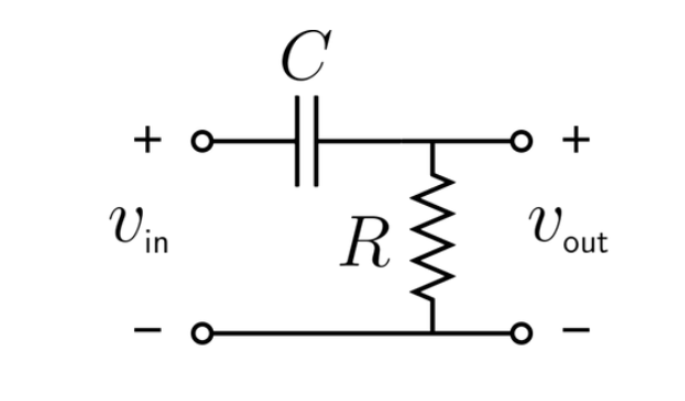
Definition: This calculator computes the cutoff frequency (\( f_c \)) for an RC high-pass filter, a basic electronic circuit that allows high-frequency signals to pass while attenuating low-frequency signals.

Purpose: It is used in electrical engineering to design RC high-pass filters for applications like audio processing, signal conditioning, and noise filtering, where low-frequency signals need to be removed.

2. How Does the Calculator Work?

The calculator uses the following formula:

  • Cutoff Frequency: \( f_c = \frac{1}{2\pi R C} \)

Where:

  • \( R \): Resistance (Ω)
  • \( C \): Capacitance (F)
  • \( f_c \): Cutoff frequency (Hz)

Steps:

  • Enter the resistance (\( R \)) and capacitance (\( C \)) with their units.
  • Convert all inputs to base units (Ω, F).
  • Calculate the cutoff frequency using the formula.
  • Convert the result to the selected output unit (Hz, kHz, MHz).
  • Display the result: if the value is less than 0.001 in the selected unit, use scientific notation; otherwise, display with 4 decimal places.

3. Importance of RC High-Pass Filter Calculation

Calculating the cutoff frequency of an RC high-pass filter is crucial for:

  • Signal Processing: Ensuring that only high-frequency signals pass through, which is essential for applications like audio crossovers or noise filtering.
  • Circuit Design: Determining the cutoff frequency to design filters that meet specific frequency response requirements.
  • Simplicity and Cost-Effectiveness: RC high-pass filters are simple and inexpensive, making them widely used in basic filtering applications.

4. Using the Calculator

Example 1: Calculate the cutoff frequency for an RC high-pass filter with \( R = 1 \, \text{kΩ} \) and \( C = 1 \, \text{µF} \):

  • Resistance (\( R \)): 1 kΩ = 1000 Ω
  • Capacitance (\( C \)): 1 µF = \( 1 \times 10^{-6} \) F
  • Cutoff Frequency (\( f_c \)): \( \frac{1}{2\pi \cdot 1000 \cdot 1 \times 10^{-6}} \approx \frac{1}{6.283 \times 10^{-3}} \approx 159.15 \, \text{Hz} \)
  • Result: \( f_c = 159.1500 \, \text{Hz} \)

Example 2 (Demonstrating Scientific Notation): Calculate the cutoff frequency for an RC high-pass filter with \( R = 1 \, \text{MΩ} \) and \( C = 1 \, \text{pF} \):

  • Resistance (\( R \)): 1 MΩ = 1000000 Ω
  • Capacitance (\( C \)): 1 pF = \( 1 \times 10^{-12} \) F
  • Cutoff Frequency (\( f_c \)): \( \frac{1}{2\pi \cdot 1000000 \cdot 1 \times 10^{-12}} \approx \frac{1}{6.283 \times 10^{-6}} \approx 159155 \, \text{Hz} \), in MHz: \( 159155 / 10^6 \approx 0.1592 \, \text{MHz} \)
  • Result: \( f_c = 0.1592 \, \text{MHz} \)

5. Frequently Asked Questions (FAQ)

Q: What is an RC high-pass filter?
A: An RC high-pass filter is a simple electronic circuit consisting of a resistor (\( R \)) and a capacitor (\( C \)) that allows high-frequency signals to pass while attenuating low-frequency signals below a certain cutoff frequency.

Q: Why is the cutoff frequency important?
A: The cutoff frequency (\( f_c \)) determines the point at which the filter starts to attenuate low-frequency signals. It is critical for ensuring the filter performs as intended in applications where low-frequency noise needs to be removed.

Q: How does the capacitor’s impedance affect the filter’s performance?
A: The capacitor’s impedance (\( Z_c \)) decreases with increasing frequency, allowing high-frequency signals to pass through more easily. For low frequencies, the impedance is high, effectively blocking those signals.

RC High-Pass Filter Calculator© - All Rights Reserved 2025