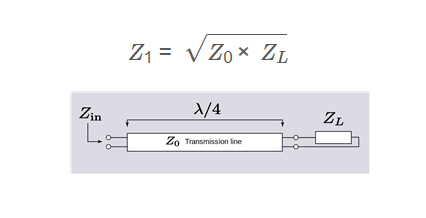
1. What is a Quarter-Wave Transformer?
Definition: A quarter-wave transformer is a transmission line section with a length equal to one-quarter of the wavelength, used to match impedances between a source and a load in RF systems.
Purpose: It is used to achieve maximum power transfer by transforming the load impedance to match the source impedance, commonly in antenna systems and RF circuits.
2. How Does the Calculator Work?
The calculator uses the following formula for the characteristic impedance of a quarter-wave transformer:
\[
Z_1 = \sqrt{Z_0 \times Z_L}
\]
Where:
- \( Z_1 \): Characteristic impedance of the transformer (converted to the selected unit: Ω, kΩ, MΩ)
- \( Z_0 \): Source impedance (converted to ohms from Ω, kΩ, or MΩ)
- \( Z_L \): Load impedance (converted to ohms from Ω, kΩ, or MΩ)
Steps:
- Enter the source impedance \( Z_0 \) and select its unit (Ω, kΩ, MΩ).
- Enter the load impedance \( Z_L \) and select its unit (Ω, kΩ, MΩ).
- Click "Calculate" to compute the characteristic impedance \( Z_1 \).
- Select the output unit for \( Z_1 \) (Ω, kΩ, MΩ) in the result section.
- The result is displayed in the selected unit.
3. Importance of Quarter-Wave Transformers
Quarter-wave transformers are essential for:
- Impedance Matching: Ensures maximum power transfer between source and load in RF systems.
- Antenna Design: Matches antenna impedances to transmission lines for optimal performance.
- RF Circuits: Reduces reflections and improves signal integrity in high-frequency circuits.
4. Using the Calculator
Examples:
- Example 1: Standard RF Matching (Output in Ω)
- \( Z_0 = 50 \, \Omega, Z_L = 100 \, \Omega \)
- \( Z_1 = \sqrt{50 \times 100} = \sqrt{5000} \approx 70.71 \, \Omega \)
- Example 2: Antenna Matching (Output in kΩ)
- \( Z_0 = 0.05 \, \text{kΩ}, Z_L = 25 \, \Omega \)
- Convert: \( Z_0 = 50 \, \Omega, Z_L = 25 \, \Omega \)
- \( Z_1 = \sqrt{50 \times 25} = \sqrt{1250} \approx 35.36 \, \Omega \)
- Output in kΩ: \( 35.36 \times 0.001 = 0.04 \, \text{kΩ} \)
- Example 3: High Impedance Load (Output in Ω)
- \( Z_0 = 75 \, \Omega, Z_L = 0.3 \, \text{kΩ} \)
- Convert: \( Z_L = 300 \, \Omega \)
- \( Z_1 = \sqrt{75 \times 300} = \sqrt{22500} = 150 \, \Omega \)
5. Frequently Asked Questions (FAQ)
Q: What is a quarter-wave transformer used for?
A: A quarter-wave transformer is used to match impedances between a source and a load in RF systems, ensuring maximum power transfer and minimizing reflections.
Q: Why is the length of the transformer a quarter wavelength?
A: A quarter wavelength ensures that the impedance transformation occurs due to the phase shift of the wave, effectively transforming the load impedance to match the source.
Q: How does unit conversion work in the calculator?
A: The calculator converts input impedances to ohms (e.g., 1 kΩ = 1000 Ω, 1 MΩ = 1,000,000 Ω). The characteristic impedance \( Z_1 \) is calculated in ohms and then converted to the selected output unit (e.g., 1000 Ω = 1 kΩ).
Quarter-Wave Transformer Impedance Calculator© - All Rights Reserved 2025
 Home
Home
 Back
Back
