1. What is Non-Inverting Op-Amp Low-Pass Filter Calculator?
Definition: This calculator computes the cutoff frequency (\( f_c \)) and gain (\( G \)) for a non-inverting op-amp low-pass filter, a circuit that allows low-frequency signals to pass while attenuating high-frequency signals without inverting the output signal.
Purpose: It is used in electrical engineering to design non-inverting op-amp low-pass filters for applications like audio processing, signal conditioning, and amplification, where high-frequency signals need to be filtered out and the output signal phase needs to be preserved.
2. How Does the Calculator Work?
The calculator uses the following formulas:
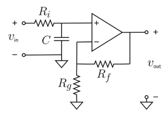
- Cutoff Frequency: \( f_c = \frac{1}{2\pi R_i C} \)
- Gain: \( G = 1 + \frac{R_f}{R_g} \)
Where:
- \( R_f \): Feedback resistance (Ω)
- \( R_g \): Ground resistance (Ω)
- \( R_i \): Input resistance (Ω)
- \( C \): Capacitance (F)
- \( f_c \): Cutoff frequency (Hz)
- \( G \): Gain (unitless)
Steps:
- Enter the feedback resistance (\( R_f \)), ground resistance (\( R_g \)), input resistance (\( R_i \)), and capacitance (\( C \)) with their units.
- Convert all inputs to base units (Ω, F).
- Calculate the cutoff frequency and gain using the formulas.
- Convert the cutoff frequency to the selected output unit (Hz, kHz, MHz).
- Display the results: if a value is less than 0.001 in the selected unit, use scientific notation; otherwise, display with 4 decimal places.
3. Importance of Non-Inverting Op-Amp Low-Pass Filter Calculation
Calculating the parameters of a non-inverting op-amp low-pass filter is crucial for:
- Signal Processing: Ensuring that only low-frequency signals pass through, which is essential for applications like audio crossovers or noise filtering.
- Amplification with Filtering: The op-amp configuration allows for both filtering and amplification, with the gain determined by the resistor ratio, making it useful in active filter designs.
- Phase Preservation: The non-inverting nature of the filter (positive gain) ensures the output signal maintains the same phase as the input, which is important in applications where phase alignment is critical.
4. Using the Calculator
Example 1: Calculate the cutoff frequency and gain for a non-inverting op-amp low-pass filter with \( R_f = 10 \, \text{kΩ} \), \( R_g = 2 \, \text{kΩ} \), \( R_i = 1 \, \text{kΩ} \), and \( C = 0.1 \, \text{µF} \):
- Feedback Resistance (\( R_f \)): 10 kΩ = 10000 Ω
- Ground Resistance (\( R_g \)): 2 kΩ = 2000 Ω
- Input Resistance (\( R_i \)): 1 kΩ = 1000 Ω
- Capacitance (\( C \)): 0.1 µF = \( 0.1 \times 10^{-6} \) F
- Cutoff Frequency (\( f_c \)): \( \frac{1}{2\pi \cdot 1000 \cdot 0.1 \times 10^{-6}} \approx \frac{1}{6.283 \times 10^{-4}} \approx 1591.55 \, \text{Hz} \), in kHz: \( 1.5916 \, \text{kHz} \)
- Gain (\( G \)): \( 1 + \frac{10000}{2000} = 1 + 5 = 6 \)
- Result: \( f_c = 1.5916 \, \text{kHz} \), \( G = 6.0000 \)
Example 2 (Demonstrating Scientific Notation): Calculate the cutoff frequency and gain for a non-inverting op-amp low-pass filter with \( R_f = 1 \, \text{kΩ} \), \( R_g = 1 \, \text{MΩ} \), \( R_i = 1 \, \text{MΩ} \), and \( C = 1 \, \text{pF} \):
- Feedback Resistance (\( R_f \)): 1 kΩ = 1000 Ω
- Ground Resistance (\( R_g \)): 1 MΩ = 1000000 Ω
- Input Resistance (\( R_i \)): 1 MΩ = 1000000 Ω
- Capacitance (\( C \)): 1 pF = \( 1 \times 10^{-12} \) F
- Cutoff Frequency (\( f_c \)): \( \frac{1}{2\pi \cdot 1000000 \cdot 1 \times 10^{-12}} \approx \frac{1}{6.283 \times 10^{-6}} \approx 159155 \, \text{Hz} \), in MHz: \( 159155 / 10^6 \approx 0.1592 \, \text{MHz} \)
- Gain (\( G \)): \( 1 + \frac{1000}{1000000} = 1 + 0.001 = 1.001 \)
- Result: \( f_c = 0.1592 \, \text{MHz} \), \( G = 1.0010 \)
5. Frequently Asked Questions (FAQ)
Q: What is a non-inverting op-amp low-pass filter?
A: A non-inverting op-amp low-pass filter is an active filter circuit that uses an operational amplifier (op-amp) in a non-inverting configuration, along with resistors and a capacitor, to allow low-frequency signals to pass while attenuating high-frequency signals without inverting the output signal.
Q: Why is the cutoff frequency important?
A: The cutoff frequency (\( f_c \)) determines the point at which the filter starts to attenuate high-frequency signals. It is critical for ensuring the filter performs as intended in applications where high-frequency noise needs to be removed.
Q: Why is the gain always positive and greater than or equal to 1?
A: In a non-inverting op-amp configuration, the gain (\( G \)) is given by \( 1 + \frac{R_f}{R_g} \), which is always positive and at least 1 because \( R_f \) and \( R_g \) are positive resistances. This ensures the output signal is amplified without inversion.
Non-Inverting Op-Amp Low-Pass Filter Calculator© - All Rights Reserved 2025
 Home
Home
 Back
Back