1. What is NE555 Timer Calculator?
Definition: This calculator computes the timing parameters for the NE555 timer IC in astable and monostable modes, including high time, low time, total period, frequency, and duty cycle for astable mode, and pulse duration for monostable mode.
Purpose: It is used in electronics to design 555 timer circuits for applications like oscillators (astable mode) and pulse generation (monostable mode), commonly used in timers, LED flashers, and pulse-width modulation (PWM) circuits.
2. How Does the Calculator Work?
The calculator uses the following formulas based on the selected mode:
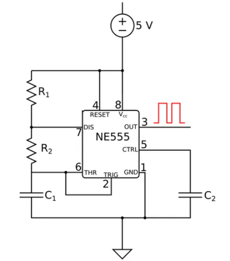
Astable Mode:
- High Time: \( T_{\text{high}} = \ln(2) \cdot (R_1 + R_2) \cdot C_1 \)
- Low Time: \( T_{\text{low}} = \ln(2) \cdot R_2 \cdot C_1 \)
- Total Period: \( T = T_{\text{high}} + T_{\text{low}} \)
- Frequency: \( f = \frac{1}{T} \)
- Duty Cycle: \( \text{Duty Cycle} = 100 \cdot \frac{T_{\text{high}}}{T_{\text{high}} + T_{\text{low}}} \)
Monostable Mode:
- Pulse Duration: \( T = \ln(3) \cdot R_1 \cdot C_1 \)
Where:
- \( R_1 \), \( R_2 \): Resistances (Ω)
- \( C_1 \): Capacitance (F)
- \( T_{\text{high}} \), \( T_{\text{low}} \), \( T \): Time intervals (s)
- \( f \): Frequency (Hz)
- \( \text{Duty Cycle} \): Percentage (%)
Steps:
- Select the mode: Astable or Monostable (defaults to Astable).
- Enter the resistances (\( R_1 \), and \( R_2 \) for astable mode) and capacitance (\( C_1 \)) with their units.
- Convert all inputs to base units (Ω, F).
- Calculate the timing parameters using the appropriate formulas.
- Convert the time and frequency results to the selected output units (s, ms, µs for time; Hz, kHz, MHz for frequency).
- Display the results: if a value is less than 0.001 in the selected unit, use scientific notation; otherwise, display with 4 decimal places.
3. Importance of NE555 Timer Calculation
Calculating the timing parameters of the NE555 timer is crucial for:
- Circuit Design: Ensuring accurate timing for oscillators, timers, and pulse generators in applications like LED flashers, alarms, and PWM controllers.
- Frequency Control: Determining the frequency and duty cycle in astable mode to meet specific requirements for waveform generation.
- Pulse Generation: Setting the pulse duration in monostable mode for applications like triggering events or generating delays.
4. Using the Calculator
Example 1 (Astable Mode): Calculate the timing parameters for a 555 timer in astable mode with \( R_1 = 1 \, \text{kΩ} \), \( R_2 = 2 \, \text{kΩ} \), and \( C_1 = 1 \, \text{µF} \):
- Mode: Astable
- Resistance \( R_1 \): 1 kΩ = 1000 Ω
- Resistance \( R_2 \): 2 kΩ = 2000 Ω
- Capacitance \( C_1 \): 1 µF = \( 1 \times 10^{-6} \) F
- High Time (\( T_{\text{high}} \)): \( \ln(2) \cdot (1000 + 2000) \cdot 1 \times 10^{-6} \approx 0.693 \times 3000 \times 10^{-6} \approx 0.002079 \, \text{s} \), in ms: \( 2.079 \, \text{ms} \)
- Low Time (\( T_{\text{low}} \)): \( \ln(2) \cdot 2000 \cdot 1 \times 10^{-6} \approx 0.693 \times 2000 \times 10^{-6} \approx 0.001386 \, \text{s} \), in ms: \( 1.386 \, \text{ms} \)
- Total Period (\( T \)): \( 0.002079 + 0.001386 \approx 0.003465 \, \text{s} \), in ms: \( 3.465 \, \text{ms} \)
- Frequency (\( f \)): \( \frac{1}{0.003465} \approx 288.6 \, \text{Hz} \)
- Duty Cycle: \( 100 \cdot \frac{0.002079}{0.002079 + 0.001386} \approx 100 \cdot \frac{0.002079}{0.003465} \approx 60 \, \% \)
- Result: \( T_{\text{high}} = 2.0790 \, \text{ms} \), \( T_{\text{low}} = 1.3860 \, \text{ms} \), \( T = 3.4650 \, \text{ms} \), \( f = 288.6000 \, \text{Hz} \), Duty Cycle = 60.0000%
Example 2 (Monostable Mode with Scientific Notation): Calculate the pulse duration for a 555 timer in monostable mode with \( R_1 = 1 \, \text{MΩ} \), \( C_1 = 1 \, \text{nF} \):
- Mode: Monostable
- Resistance \( R_1 \): 1 MΩ = 1000000 Ω
- Capacitance \( C_1 \): 1 nF = \( 1 \times 10^{-9} \) F
- Pulse Duration (\( T \)): \( \ln(3) \cdot 1000000 \cdot 1 \times 10^{-9} \approx 1.0986 \times 1000000 \times 10^{-9} \approx 0.0000010986 \, \text{s} \), in µs: \( 1.0986 \, \text{µs} \)
- Result: \( T = 1.0986 \, \text{µs} \)
5. Frequently Asked Questions (FAQ)
Q: What is the difference between astable and monostable modes of the 555 timer?
A: In astable mode, the 555 timer generates a continuous square wave output, oscillating between high and low states, making it suitable for oscillators. In monostable mode, the 555 timer generates a single pulse of a fixed duration when triggered, making it suitable for pulse generation.
Q: Why does the duty cycle in astable mode depend on \( R_1 \) and \( R_2 \)?
A: The duty cycle depends on \( R_1 \) and \( R_2 \) because \( T_{\text{high}} \) is determined by \( R_1 + R_2 \), while \( T_{\text{low}} \) is determined by \( R_2 \). The ratio of \( T_{\text{high}} \) to the total period (\( T_{\text{high}} + T_{\text{low}} \)) gives the duty cycle.
Q: Can the duty cycle in astable mode be less than 50%?
A: Yes, but it requires additional circuitry (e.g., a diode) because the standard 555 astable configuration always has a duty cycle greater than 50% since \( T_{\text{high}} \) (charging through \( R_1 + R_2 \)) is longer than \( T_{\text{low}} \) (discharging through \( R_2 \)).
 Home
Home
 Back
Back