Home Back

N-Way Power Divider Calculator

1. What is a Loss Total Calculator?

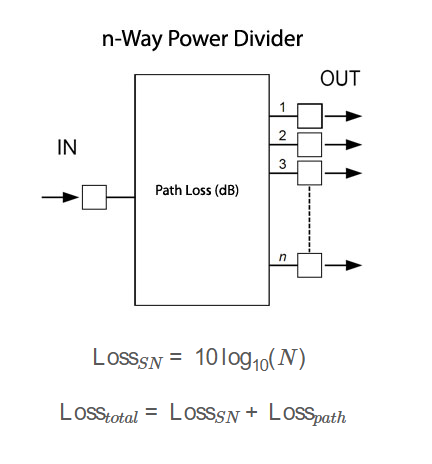
Definition: This calculator determines the total loss (\( \text{Loss}_{total} \)) of an \( N \)-way power divider, accounting for both the splitting loss (\( \text{Loss}_{SN} \)) due to power division and the additional path loss (\( \text{Loss}_{path} \)).

Purpose: It helps RF engineers estimate the total signal loss in power divider systems, which is critical for link budget analysis and system design in applications like RF signal distribution and phased array systems.

2. How Does the Calculator Work?

The calculator uses the following formulas to compute the splitting loss and total loss:

Splitting Loss (\( \text{Loss}_{SN} \)) in dB: \[ \text{Loss}_{SN} = 10 \log_{10}(N) \]

Total Loss (\( \text{Loss}_{total} \)) in dB: \[ \text{Loss}_{total} = \text{Loss}_{SN} + \text{Loss}_{path} \]

Where:

  • \( N \): Number of output ports
  • \( \text{Loss}_{path} \): Path loss in dB (e.g., due to cables, connectors, or material losses)
  • \( \text{Loss}_{SN} \): Splitting loss in dB
  • \( \text{Loss}_{total} \): Total loss in dB

Steps:

  • Enter the number of ports \( N \) (must be an integer ≥ 2).
  • Enter the path loss \( \text{Loss}_{path} \) in dB (typically 0.5–2 dB for practical systems).
  • Click "Calculate" to compute \( \text{Loss}_{SN} \) and \( \text{Loss}_{total} \).
  • Results are displayed in dB.

3. Importance of Loss Total Calculations

Calculating total loss is essential for:

  • Link Budget Analysis: Ensures accurate prediction of signal levels after power division, accounting for both splitting and path losses.
  • System Design: Helps engineers select appropriate amplifiers or components to compensate for losses in RF systems.
  • Performance Optimization: Minimizes unexpected signal degradation in applications like signal distribution or antenna arrays.

4. Using the Calculator

Examples:

  • Example 1: \( N = 2 \), \( \text{Loss}_{path} = 0.5 \, \text{dB} \)
    • \( \text{Loss}_{SN} = 10 \log_{10}(2) \approx 3.01 \, \text{dB} \)
    • \( \text{Loss}_{total} = 3.01 + 0.5 = 3.51 \, \text{dB} \)
  • Example 2: \( N = 4 \), \( \text{Loss}_{path} = 1.2 \, \text{dB} \)
    • \( \text{Loss}_{SN} = 10 \log_{10}(4) \approx 6.02 \, \text{dB} \)
    • \( \text{Loss}_{total} = 6.02 + 1.2 = 7.22 \, \text{dB} \)
  • Example 3: \( N = 3 \), \( \text{Loss}_{path} = 0.8 \, \text{dB} \)
    • \( \text{Loss}_{SN} = 10 \log_{10}(3) \approx 4.77 \, \text{dB} \)
    • \( \text{Loss}_{total} = 4.77 + 0.8 = 5.57 \, \text{dB} \)

5. Frequently Asked Questions (FAQ)

Q: What is splitting loss (\( \text{Loss}_{SN} \))?
A: Splitting loss is the theoretical loss due to dividing power equally among \( N \) ports. It’s calculated as \( 10 \log_{10}(N) \) dB and represents the reduction in power per port compared to the input.

Q: What contributes to path loss (\( \text{Loss}_{path} \))?
A: Path loss includes losses from cables, connectors, dielectric materials, conductor resistance, and impedance mismatches. Typical values range from 0.5 to 2 dB in practical systems.

Q: How does the number of ports affect total loss?
A: Increasing \( N \) increases \( \text{Loss}_{SN} \), which in turn increases \( \text{Loss}_{total} \). This reduces the signal strength at each output, potentially requiring amplification.

Loss Total Calculator© - All Rights Reserved 2025