1. What is a Microstrip Impedance Calculator?
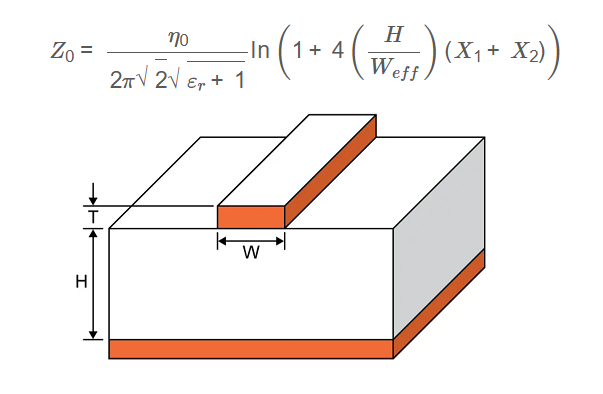
Definition: This calculator determines the characteristic impedance \( Z_0 \) of a microstrip transmission line based on the dielectric constant of the substrate (\( \varepsilon_r \)), substrate height (\( H \)), trace width (\( W \)), and trace thickness (\( t \)).
Purpose: It helps RF and PCB designers calculate the impedance of microstrip lines to ensure signal integrity, minimize reflections, and achieve proper impedance matching in high-frequency circuits.
2. How Does the Calculator Work?
The calculator uses the following formula to compute the characteristic impedance:
Characteristic Impedance \( Z_0 \):
\[
Z_{0} = \frac{\eta_0}{2\pi \sqrt{2} \sqrt{\varepsilon_r + 1}} \ln \left( 1 + 4 \left( \frac{H}{W_{eff}} \right) \left( X_1 + X_2 \right) \right)
\]
Where:
\[
W_{eff} = W + \left( \frac{t}{\pi} \right) \ln \left\{ \frac{4e}{\sqrt{\left(\frac{t}{H}\right)^2 + \left(\frac{t}{W \pi + 1.1 t \pi}\right)^2}} \right\} \frac{\varepsilon_r + 1}{2 \varepsilon_r}
\]
\[
X_1 = 4 \left( \frac{14 \varepsilon_r + 8}{11 \varepsilon_r} \right) \left( \frac{H}{W_{eff}} \right)
\]
\[
X_2 = \sqrt{16 \left( \frac{H}{W_{eff}} \right)^2 \left( \frac{14 \varepsilon_r + 8}{11 \varepsilon_r} \right)^2 + \left( \frac{\varepsilon_r + 1}{2 \varepsilon_r} \right) \pi^2}
\]
Where:
- \( Z_0 \): Characteristic impedance in ohms
- \( \eta_0 \approx 376.730313461 \): Free-space impedance in ohms
- \( \varepsilon_r \): Dielectric constant of the substrate
- \( H \): Substrate height (distance to ground plane)
- \( W \): Width of the trace
- \( t \): Thickness of the trace
- \( W_{eff} \): Effective width of the trace, accounting for fringing fields
Unit Conversions:
- Input Dimensions (\( H, W, t \)):
- 1 mm = 39.3701 mils
- 1 μm = 0.0393701 mils
- Output Impedance (\( Z_0 \)):
- 1 ohm = 1000 mΩ
Steps:
- Enter the dielectric constant \( \varepsilon_r \).
- Enter the substrate height \( H \), trace width \( W \), and trace thickness \( t \), selecting the unit for each (mils, mm, or μm).
- Click "Calculate" to compute \( Z_0 \).
- The result is initially displayed in ohms.
- Select a different unit for \( Z_0 \) (ohms or mΩ) from the dropdown after the result to convert the displayed value.
3. Importance of Microstrip Impedance Calculation
Calculating the impedance of a microstrip is crucial for:
- Signal Integrity: Ensures minimal distortion in high-frequency signals.
- Impedance Matching: Reduces reflections by matching the transmission line impedance to the source and load.
- Design Optimization: Helps PCB designers select appropriate trace geometries for controlled impedance lines.
4. Using the Calculator
Examples:
- Example 1: \( \varepsilon_r = 4.5 \), \( H = 30 \) mils, \( W = 10 \) mils, \( t = 1.4 \) mils, Result in ohms
- \( W_{eff} = 10 + \left( \frac{1.4}{\pi} \right) \ln \left\{ \frac{4e}{\sqrt{\left(\frac{1.4}{30}\right)^2 + \left(\frac{1.4}{10 \pi + 1.1 \cdot 1.4 \pi}\right)^2}} \right\} \frac{4.5 + 1}{2 \cdot 4.5} \approx 10.74 \)
- \( X_1 = 4 \left( \frac{14 \cdot 4.5 + 8}{11 \cdot 4.5} \right) \left( \frac{30}{10.74} \right) \approx 15.79 \)
- \( X_2 = \sqrt{16 \left( \frac{30}{10.74} \right)^2 \left( \frac{14 \cdot 4.5 + 8}{11 \cdot 4.5} \right)^2 + \left( \frac{4.5 + 1}{2 \cdot 4.5} \right) \pi^2} \approx 15.95 \)
- \( Z_0 = \frac{376.730313461}{2 \pi \sqrt{2} \sqrt{4.5 + 1}} \ln \left( 1 + 4 \left( \frac{30}{10.74} \right) (15.79 + 15.95) \right) \approx 105.94 \, \text{ohms} \)
- Example 2: \( \varepsilon_r = 3.9 \), \( H = 0.762 \) mm, \( W = 254 \) μm, \( t = 0.0356 \) mm, Result in mΩ
- Convert: \( H = 0.762 \times 39.3701 \approx 30 \), \( W = 254 \times 0.0393701 \approx 10 \), \( t = 0.0356 \times 39.3701 \approx 1.4 \)
- \( W_{eff} \approx 10.75 \), \( X_1 \approx 15.82 \), \( X_2 \approx 15.95 \)
- \( Z_0 = \frac{376.730313461}{2 \pi \sqrt{2} \sqrt{3.9 + 1}} \ln \left( 1 + 4 \left( \frac{30}{10.75} \right) (15.82 + 15.95) \right) \approx 111.46 \, \text{ohms} \)
- Result in mΩ: \( Z_0 = 111.46 \times 1000 = 111460 \, \text{mΩ} \)
- Example 3: \( \varepsilon_r = 4.2 \), \( H = 762 \) μm, \( W = 10 \) mils, \( t = 1.4 \) mils, Result in ohms
- Convert: \( H = 762 \times 0.0393701 \approx 30 \), \( W = 10 \), \( t = 1.4 \)
- \( W_{eff} \approx 10.74 \), \( X_1 \approx 15.80 \), \( X_2 \approx 15.95 \)
- \( Z_0 = \frac{376.730313461}{2 \pi \sqrt{2} \sqrt{4.2 + 1}} \ln \left( 1 + 4 \left( \frac{30}{10.74} \right) (15.80 + 15.95) \right) \approx 108.67 \, \text{ohms} \)
5. Frequently Asked Questions (FAQ)
Q: What is a microstrip transmission line?
A: A microstrip is a flat conductor on a dielectric substrate over a ground plane, widely used in RF and microwave circuits for signal transmission.
Q: Why is impedance calculation important for microstrips?
A: Accurate impedance calculation ensures proper signal integrity, minimizes reflections, and achieves impedance matching in high-frequency applications.
Q: What factors affect the accuracy of this calculation?
A: The formula assumes ideal conditions. Real-world factors like frequency-dependent dielectric constants, copper roughness, and manufacturing tolerances can affect accuracy.
Microstrip Impedance Calculator© - All Rights Reserved 2025
 Home
Home
 Back
Back