Home Back

Inverting Op-Amp Low-Pass Filter Calculator

Inverting Op-Amp Low-Pass Filter Formula

1. What is Inverting Op-Amp Low-Pass Filter Calculator?

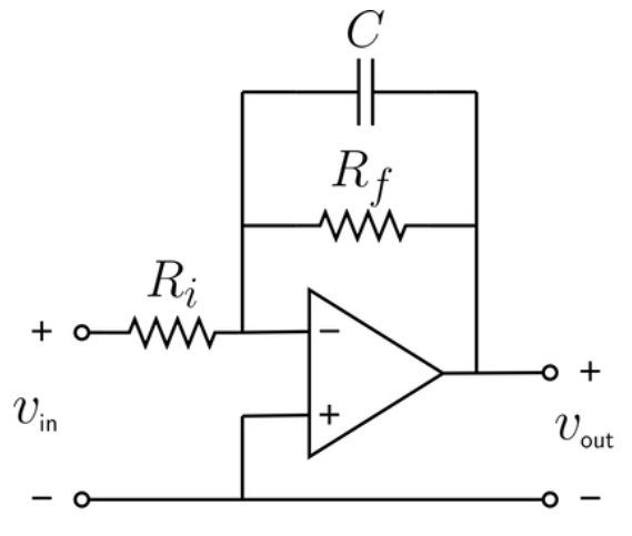
Definition: This calculator computes the cutoff frequency (\( f_c \)) and gain (\( G \)) for an inverting op-amp low-pass filter, a circuit that allows low-frequency signals to pass while attenuating high-frequency signals and inverting the output signal.

Purpose: It is used in electrical engineering to design inverting op-amp low-pass filters for applications like audio processing, signal conditioning, and amplification, where high-frequency signals need to be filtered out and the output signal needs to be inverted.

2. How Does the Calculator Work?

The calculator uses the following formulas:

  • Cutoff Frequency: \( f_c = \frac{1}{2\pi R_f C} \)
  • Gain: \( G = -\frac{R_f}{R_i} \)

Where:

  • \( R_f \): Feedback resistance (Ω)
  • \( R_i \): Input resistance (Ω)
  • \( C \): Capacitance (F)
  • \( f_c \): Cutoff frequency (Hz)
  • \( G \): Gain (unitless)

Steps:

  • Enter the feedback resistance (\( R_f \)), input resistance (\( R_i \)), and capacitance (\( C \)) with their units.
  • Convert all inputs to base units (Ω, F).
  • Calculate the cutoff frequency and gain using the formulas.
  • Convert the cutoff frequency to the selected output unit (Hz, kHz, MHz).
  • Display the results: if a value is less than 0.001 in the selected unit, use scientific notation; otherwise, display with 4 decimal places.

3. Importance of Inverting Op-Amp Low-Pass Filter Calculation

Calculating the parameters of an inverting op-amp low-pass filter is crucial for:

  • Signal Processing: Ensuring that only low-frequency signals pass through, which is essential for applications like audio crossovers or noise filtering.
  • Amplification with Filtering: The op-amp configuration allows for both filtering and amplification, with the gain determined by the resistor ratio, making it useful in active filter designs.
  • Phase Inversion: The inverting nature of the filter (negative gain) can be used in applications where a 180° phase shift is desired.

4. Using the Calculator

Example 1: Calculate the cutoff frequency and gain for an inverting op-amp low-pass filter with \( R_f = 10 \, \text{kΩ} \), \( R_i = 2 \, \text{kΩ} \), and \( C = 0.1 \, \text{µF} \):

  • Feedback Resistance (\( R_f \)): 10 kΩ = 10000 Ω
  • Input Resistance (\( R_i \)): 2 kΩ = 2000 Ω
  • Capacitance (\( C \)): 0.1 µF = \( 0.1 \times 10^{-6} \) F
  • Cutoff Frequency (\( f_c \)): \( \frac{1}{2\pi \cdot 10000 \cdot 0.1 \times 10^{-6}} \approx \frac{1}{6.283 \times 10^{-3}} \approx 159.15 \, \text{Hz} \)
  • Gain (\( G \)): \( -\frac{10000}{2000} = -5 \)
  • Result: \( f_c = 159.1500 \, \text{Hz} \), \( G = -5.0000 \)

Example 2 (Demonstrating Scientific Notation): Calculate the cutoff frequency and gain for an inverting op-amp low-pass filter with \( R_f = 1 \, \text{MΩ} \), \( R_i = 1 \, \text{kΩ} \), and \( C = 1 \, \text{pF} \):

  • Feedback Resistance (\( R_f \)): 1 MΩ = 1000000 Ω
  • Input Resistance (\( R_i \)): 1 kΩ = 1000 Ω
  • Capacitance (\( C \)): 1 pF = \( 1 \times 10^{-12} \) F
  • Cutoff Frequency (\( f_c \)): \( \frac{1}{2\pi \cdot 1000000 \cdot 1 \times 10^{-12}} \approx \frac{1}{6.283 \times 10^{-6}} \approx 159155 \, \text{Hz} \), in MHz: \( 159155 / 10^6 \approx 0.1592 \, \text{MHz} \)
  • Gain (\( G \)): \( -\frac{1000000}{1000} = -1000 \)
  • Result: \( f_c = 0.1592 \, \text{MHz} \), \( G = -1000.0000 \)

5. Frequently Asked Questions (FAQ)

Q: What is an inverting op-amp low-pass filter?
A: An inverting op-amp low-pass filter is an active filter circuit that uses an operational amplifier (op-amp) in an inverting configuration, along with a resistor and capacitor, to allow low-frequency signals to pass while attenuating high-frequency signals and inverting the output signal.

Q: Why is the cutoff frequency important?
A: The cutoff frequency (\( f_c \)) determines the point at which the filter starts to attenuate high-frequency signals. It is critical for ensuring the filter performs as intended in applications where high-frequency noise needs to be removed.

Q: Why is the gain negative in an inverting op-amp filter?
A: The negative gain indicates that the output signal is inverted (180° phase shift) relative to the input signal, which is a characteristic of the inverting op-amp configuration. This phase inversion can be useful in certain applications but may require additional consideration if phase alignment is critical.

Inverting Op-Amp Low-Pass Filter Calculator© - All Rights Reserved 2025