1. What is Inverting Buck-Boost Converter Calculator?
Definition: This calculator computes the duty cycle (\( D \)) and inductance (\( L \)) for an inverting buck-boost converter, a type of DC-DC converter that can step up or step down the input voltage while inverting the output polarity.
Purpose: It is used in electrical engineering to design inverting buck-boost converters for applications like power supplies, battery management systems, and LED drivers, where the output voltage needs to be either higher or lower than the input voltage with an inverted polarity.
2. How Does the Calculator Work?
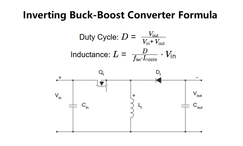
The calculator uses the following formulas:
- Duty Cycle: \( D = \frac{V_{\text{out}}}{V_{\text{in}} + V_{\text{out}}} \)
- Inductance: \( L = \frac{D}{f_{\text{sw}} \cdot I_{\text{ripple}}} \cdot V_{\text{in}} \)
Where:
- \( V_{\text{in}} \): Input voltage (V)
- \( V_{\text{out}} \): Output voltage (V)
- \( f_{\text{sw}} \): Switching frequency (Hz)
- \( I_{\text{ripple}} \): Maximum ripple current (A)
- \( D \): Duty cycle (unitless, between 0 and 1)
- \( L \): Inductance (H)
Steps:
- Enter the input voltage (\( V_{\text{in}} \)), output voltage (\( V_{\text{out}} \)), switching frequency (\( f_{\text{sw}} \)), and maximum ripple current (\( I_{\text{ripple}} \)) with their units.
- Convert all inputs to base units (V, Hz, A).
- Calculate the duty cycle (\( D \)) using the formula.
- Calculate the inductance (\( L \)) using the duty cycle and other inputs.
- Convert the inductance to the selected output unit (H, mH, µH).
- Display the results: if a value is less than 0.001 in the selected unit, use scientific notation; otherwise, display with 4 decimal places.
3. Importance of Inverting Buck-Boost Converter Calculation
Calculating the duty cycle and inductance of an inverting buck-boost converter is crucial for:
- Voltage Regulation: Ensuring the converter can step up or step down the input voltage to the desired output voltage, with the correct polarity inversion.
- Efficiency Optimization: Selecting the appropriate inductance to minimize ripple current and improve the efficiency of the converter.
- Component Selection: Determining the duty cycle and inductance helps in choosing the right components (e.g., inductor, switch) for the converter design.
4. Using the Calculator
Example 1 (Buck Mode): Calculate the duty cycle and inductance for an inverting buck-boost converter with \( V_{\text{in}} = 12 \, \text{V} \), \( V_{\text{out}} = 5 \, \text{V} \), \( f_{\text{sw}} = 100 \, \text{kHz} \), and \( I_{\text{ripple}} = 0.1 \, \text{A} \):
- Input Voltage (\( V_{\text{in}} \)): 12 V
- Output Voltage (\( V_{\text{out}} \)): 5 V
- Switching Frequency (\( f_{\text{sw}} \)): 100 kHz = \( 100 \times 10^3 \) Hz
- Maximum Ripple Current (\( I_{\text{ripple}} \)): 0.1 A
- Duty Cycle (\( D \)): \( \frac{5}{12 + 5} = \frac{5}{17} \approx 0.2941 \)
- Inductance (\( L \)): \( \frac{0.2941}{100 \times 10^3 \cdot 0.1} \cdot 12 = \frac{0.2941}{10000} \cdot 12 \approx 0.0003529 \, \text{H} \), in mH: \( 0.0003529 \times 1000 = 0.3529 \, \text{mH} \), in µH: \( 0.3529 \times 1000 = 352.9 \, \text{µH} \)
- Result: \( D = 0.2941 \), \( L = 352.9000 \, \text{µH} \)
Example 2 (Boost Mode with Scientific Notation): Calculate the duty cycle and inductance for an inverting buck-boost converter with \( V_{\text{in}} = 3 \, \text{V} \), \( V_{\text{out}} = 9 \, \text{V} \), \( f_{\text{sw}} = 1 \, \text{MHz} \), and \( I_{\text{ripple}} = 10 \, \text{mA} \):
- Input Voltage (\( V_{\text{in}} \)): 3 V
- Output Voltage (\( V_{\text{out}} \)): 9 V
- Switching Frequency (\( f_{\text{sw}} \)): 1 MHz = \( 1 \times 10^6 \) Hz
- Maximum Ripple Current (\( I_{\text{ripple}} \)): 10 mA = \( 10 \times 10^{-3} = 0.01 \) A
- Duty Cycle (\( D \)): \( \frac{9}{3 + 9} = \frac{9}{12} = 0.75 \)
- Inductance (\( L \)): \( \frac{0.75}{1 \times 10^6 \cdot 0.01} \cdot 3 = \frac{0.75}{10000} \cdot 3 = 0.000225 \, \text{H} \), in µH: \( 0.000225 \times 10^6 = 225 \, \text{µH} \)
- Result: \( D = 0.7500 \), \( L = 225.0000 \, \text{µH} \)
5. Frequently Asked Questions (FAQ)
Q: What is an inverting buck-boost converter?
A: An inverting buck-boost converter is a type of DC-DC converter that can step up or step down the input voltage while inverting the output polarity (i.e., the output voltage is negative relative to the input). It operates in buck mode (\( V_{\text{out}} < V_{\text{in}} \)) when \( D < 0.5 \) and in boost mode (\( V_{\text{out}} > V_{\text{in}} \)) when \( D > 0.5 \).
Q: Why is the duty cycle important?
A: The duty cycle (\( D \)) determines the operating mode of the converter (buck or boost) and affects the output voltage. It also influences the inductance calculation, which is critical for ensuring proper operation and minimizing ripple current.
Q: How does the ripple current affect the inductance?
A: The maximum ripple current (\( I_{\text{ripple}} \)) inversely affects the inductance (\( L \)). A smaller ripple current requires a larger inductance to maintain stable operation, while a larger ripple current allows for a smaller inductance, which can reduce the size and cost of the inductor.
Inverting Buck-Boost Converter Calculator© - All Rights Reserved 2025
 Home
Home
 Back
Back