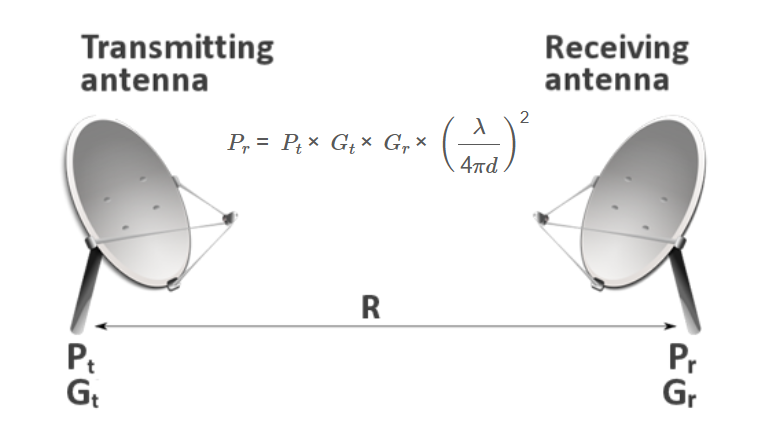
1. What is the Friis Transmission Equation?
Definition: The Friis Transmission Equation calculates the power received by an antenna (\( P_r \)) from a transmitted signal (\( P_t \)) in free space, considering antenna gains and the path loss due to distance and frequency.
Purpose: It is used to estimate the received signal strength in wireless communication systems, such as satellite links, Wi-Fi, and cellular networks, helping engineers design reliable links.
2. How Does the Calculator Work?
The calculator uses the Friis Transmission Equation:
\[
P_r = P_t \times G_t \times G_r \times \left(\frac{\lambda}{4 \pi d}\right)^2
\]
Where:
- \( P_r \): Received power (converted to selected unit: watts, mW, dBm)
- \( P_t \): Transmitted power (converted to watts from watts, mW, or dBm)
- \( G_t \): Transmitter gain (converted from dBi to linear)
- \( G_r \): Receiver gain (converted from dBi to linear)
- \( \lambda \): Wavelength (\( \lambda = \frac{c}{f} \), in meters)
- \( d \): Distance (converted to meters from m, km, ft, or miles)
- \( c \): Speed of light (\( 3 \times 10^8 \, \text{m/s} \))
- \( f \): Frequency (converted to Hz from Hz, kHz, MHz, or GHz)
Steps:
- Enter the transmitted power \( P_t \) and select its unit (watts, mW, dBm).
- Enter the transmitter gain \( G_t \) and receiver gain \( G_r \) in dBi.
- Enter the distance \( d \) and select its unit (meters, km, feet, or miles).
- Enter the frequency \( f \) and select its unit (Hz, kHz, MHz, GHz).
- Click "Calculate" to compute the received power.
- Select the output unit for received power (watts, mW, dBm) in the result section.
- The result is displayed in the selected unit.
3. Importance of Friis Transmission Calculations
Friis Transmission calculations are essential for:
- Link Budget Analysis: Determines the received signal strength to ensure reliable communication.
- System Design: Helps in selecting appropriate transmitter power, antenna gains, and frequencies for wireless systems.
- Performance Optimization: Assists in optimizing the placement of antennas to minimize path loss.
4. Using the Calculator
Examples:
- Example 1: Wi-Fi Link (Output in dBm)
- \( P_t = 1 \, \text{watt}, G_t = 5 \, \text{dBi}, G_r = 3 \, \text{dBi}, d = 100 \, \text{m}, f = 2.4 \, \text{GHz} \)
- \( G_t = 10^{5/10} \approx 3.16, G_r = 10^{3/10} \approx 2 \)
- \( \lambda = \frac{3 \times 10^8}{2.4 \times 10^9} \approx 0.125 \, \text{m} \)
- \( P_r = 1 \times 3.16 \times 2 \times \left(\frac{0.125}{4 \pi \times 100}\right)^2 \approx 3.95 \times 10^{-5} \, \text{watts} \)
- Output in dBm: \( 10 \times \log_{10}(3.95 \times 10^{-5}) + 30 \approx -14.03 \, \text{dBm} \)
- Example 2: Short Distance (Output in mW)
- \( P_t = 100 \, \text{mW}, G_t = 2 \, \text{dBi}, G_r = 2 \, \text{dBi}, d = 10 \, \text{m}, f = 900 \, \text{MHz} \)
- Convert: \( P_t = 0.1 \, \text{watts}, f = 900 \times 10^6 \, \text{Hz} \)
- \( G_t = G_r = 10^{2/10} \approx 1.58 \)
- \( \lambda = \frac{3 \times 10^8}{900 \times 10^6} \approx 0.333 \, \text{m} \)
- \( P_r = 0.1 \times 1.58 \times 1.58 \times \left(\frac{0.333}{4 \pi \times 10}\right)^2 \approx 5.59 \times 10^{-4} \, \text{watts} \)
- Output in mW: \( 5.59 \times 10^{-4} \times 1000 \approx 0.56 \, \text{mW} \)
- Example 3: Long Distance (Output in watts)
- \( P_t = 30 \, \text{dBm}, G_t = 10 \, \text{dBi}, G_r = 10 \, \text{dBi}, d = 1 \, \text{km}, f = 100 \, \text{MHz} \)
- Convert: \( P_t = 10^{(30-30)/10} = 1 \, \text{watt}, d = 1000 \, \text{m}, f = 100 \times 10^6 \, \text{Hz} \)
- \( G_t = G_r = 10^{10/10} = 10 \)
- \( \lambda = \frac{3 \times 10^8}{100 \times 10^6} = 3 \, \text{m} \)
- \( P_r = 1 \times 10 \times 10 \times \left(\frac{3}{4 \pi \times 1000}\right)^2 \approx 5.69 \times 10^{-6} \, \text{watts} \)
5. Frequently Asked Questions (FAQ)
Q: What does the Friis Transmission Equation calculate?
A: It calculates the power received by an antenna in free space, considering the transmitted power, antenna gains, distance, and frequency.
Q: Why are gains input in dBi?
A: dBi (decibels relative to isotropic) is a common unit for antenna gain. The calculator converts dBi to linear gain for use in the equation.
Q: How does unit conversion work in the calculator?
A: The calculator converts transmitted power to watts (from watts, mW, or dBm), distance to meters (from m, km, ft, or miles), and frequency to Hz (from Hz, kHz, MHz, or GHz). The received power is then converted to the selected output unit (watts, mW, dBm).
Friis Transmission Calculator© - All Rights Reserved 2025
 Home
Home
 Back
Back
