1. What is Flyback Converter Calculator?
Definition: This calculator computes the duty cycle (\( D \)), peak currents (\( I_{S,\text{peak}}, I_{P,\text{peak}} \)), and inductances (\( L_S, L_P \)) of the primary and secondary windings of a flyback transformer in a flyback converter.
Purpose: It is used in power electronics to design flyback converters, which are commonly found in low-power DC-DC conversion applications such as power supplies for laptops, USB chargers, and LED drivers.
2. How Does the Calculator Work?
The calculator uses the following formulas:
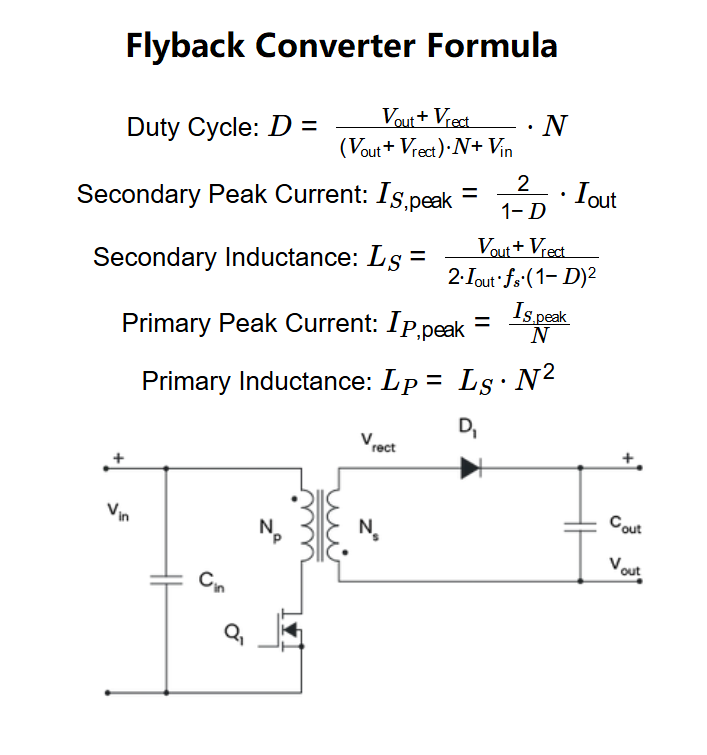
- Duty Cycle: \( D = \frac{V_{\text{out}} + V_{\text{rect}}}{(V_{\text{out}} + V_{\text{rect}}) \cdot N + V_{\text{in}}} \cdot N \)
- Secondary Peak Current: \( I_{S,\text{peak}} = \frac{2}{1 - D} \cdot I_{\text{out}} \)
- Secondary Inductance: \( L_S = \frac{V_{\text{out}} + V_{\text{rect}}}{2 \cdot I_{\text{out}} \cdot f_s \cdot (1 - D)^2} \)
- Primary Peak Current: \( I_{P,\text{peak}} = \frac{I_{S,\text{peak}}}{N} \)
- Primary Inductance: \( L_P = L_S \cdot N^2 \)
Where:
- \( D \): Duty cycle (unitless, between 0 and 1)
- \( V_{\text{in}} \): Input voltage (V)
- \( V_{\text{out}} \): Output voltage (V)
- \( V_{\text{rect}} \): Voltage rectified by diode \( D_1 \) (V)
- \( N \): Windings ratio (\( N_p / N_s \), unitless)
- \( I_{\text{out}} \): Output current (A)
- \( f_s \): Switching frequency (Hz)
- \( I_{S,\text{peak}} \): Peak current through the secondary winding (A)
- \( L_S \): Inductance of the secondary winding (H)
- \( I_{P,\text{peak}} \): Peak current through the primary winding (A)
- \( L_P \): Inductance of the primary winding (H)
Steps:
- Enter the input voltage (\( V_{\text{in}} \)), output voltage (\( V_{\text{out}} \)), rectified voltage (\( V_{\text{rect}} \)), windings ratio (\( N \)), output current (\( I_{\text{out}} \)), and switching frequency (\( f_s \)) with their units.
- Convert all inputs to base units (V, A, Hz).
- Calculate the duty cycle, peak currents, and inductances using the formulas.
- Convert the results to the selected output units.
- Display the results: if a value is less than 0.001 in the selected unit, use scientific notation; otherwise, display with 4 decimal places.
3. Importance of Flyback Converter Calculation
Calculating the parameters of a flyback converter is crucial for:
- Power Supply Design: Ensuring the flyback converter can deliver the required output voltage and current for applications like chargers or LED drivers.
- Efficiency: Optimizing the duty cycle to improve the efficiency of the converter and reduce losses.
- Component Selection: Determining the appropriate inductance values and current ratings for the transformer windings to prevent saturation or overheating.
4. Using the Calculator
Example 1: Calculate the parameters for a flyback converter with \( V_{\text{in}} = 12 \, \text{V} \), \( V_{\text{out}} = 5 \, \text{V} \), \( V_{\text{rect}} = 0.7 \, \text{V} \), \( N = 2 \), \( I_{\text{out}} = 1 \, \text{A} \), and \( f_s = 50 \, \text{kHz} \):
- Input Voltage (\( V_{\text{in}} \)): 12 V
- Output Voltage (\( V_{\text{out}} \)): 5 V
- Rectified Voltage (\( V_{\text{rect}} \)): 0.7 V
- Windings Ratio (\( N \)): 2
- Output Current (\( I_{\text{out}} \)): 1 A
- Switching Frequency (\( f_s \)): 50 kHz = \( 50 \times 10^3 \) Hz
- Duty Cycle (\( D \)): \( \frac{5 + 0.7}{(5 + 0.7) \cdot 2 + 12} \cdot 2 = \frac{5.7}{5.7 \cdot 2 + 12} \cdot 2 = \frac{5.7}{11.4 + 12} \cdot 2 = \frac{5.7}{23.4} \cdot 2 \approx 0.4872 \)
- Secondary Peak Current (\( I_{S,\text{peak}} \)): \( \frac{2}{1 - 0.4872} \cdot 1 \approx \frac{2}{0.5128} \approx 3.8997 \, \text{A} \)
- Secondary Inductance (\( L_S \)): \( \frac{5 + 0.7}{2 \cdot 1 \cdot 50 \times 10^3 \cdot (1 - 0.4872)^2} = \frac{5.7}{2 \cdot 50 \times 10^3 \cdot (0.5128)^2} \approx \frac{5.7}{100 \times 10^3 \cdot 0.2630} \approx 2.1673 \times 10^{-4} \, \text{H} = 0.2167 \, \text{mH} \)
- Primary Peak Current (\( I_{P,\text{peak}} \)): \( \frac{3.8997}{2} \approx 1.9498 \, \text{A} \)
- Primary Inductance (\( L_P \)): \( 2.1673 \times 10^{-4} \cdot 2^2 \approx 2.1673 \times 10^{-4} \cdot 4 \approx 8.6692 \times 10^{-4} \, \text{H} = 0.8669 \, \text{mH} \)
- Result: \( D = 0.4872 \), \( I_{S,\text{peak}} = 3.8997 \, \text{A} \), \( L_S = 0.2167 \, \text{mH} \), \( I_{P,\text{peak}} = 1.9498 \, \text{A} \), \( L_P = 0.8669 \, \text{mH} \)
Example 2 (Demonstrating Scientific Notation): Calculate the parameters for a flyback converter with \( V_{\text{in}} = 100 \, \text{V} \), \( V_{\text{out}} = 5 \, \text{V} \), \( V_{\text{rect}} = 0.7 \, \text{V} \), \( N = 10 \), \( I_{\text{out}} = 0.01 \, \text{mA} \), and \( f_s = 1 \, \text{MHz} \):
- Input Voltage (\( V_{\text{in}} \)): 100 V
- Output Voltage (\( V_{\text{out}} \)): 5 V
- Rectified Voltage (\( V_{\text{rect}} \)): 0.7 V
- Windings Ratio (\( N \)): 10
- Output Current (\( I_{\text{out}} \)): 0.01 mA = \( 0.01 \times 10^{-3} = 10^{-5} \, \text{A} \)
- Switching Frequency (\( f_s \)): 1 MHz = \( 1 \times 10^6 \) Hz
- Duty Cycle (\( D \)): \( \frac{5 + 0.7}{(5 + 0.7) \cdot 10 + 100} \cdot 10 = \frac{5.7}{5.7 \cdot 10 + 100} \cdot 10 = \frac{5.7}{57 + 100} \cdot 10 = \frac{5.7}{157} \cdot 10 \approx 0.3631 \)
- Secondary Peak Current (\( I_{S,\text{peak}} \)): \( \frac{2}{1 - 0.3631} \cdot 10^{-5} \approx \frac{2}{0.6369} \cdot 10^{-5} \approx 3.1392 \times 10^{-5} \, \text{A} \), in mA: \( 3.1392 \times 10^{-5} \times 10^3 = 3.1392 \times 10^{-2} \, \text{mA} = 0.0314 \, \text{mA} \), in µA: \( 3.1392 \times 10^{-5} \times 10^6 = 31.392 \, \text{µA} \)
- Secondary Inductance (\( L_S \)): \( \frac{5 + 0.7}{2 \cdot 10^{-5} \cdot 1 \times 10^6 \cdot (1 - 0.3631)^2} = \frac{5.7}{2 \cdot 10^{-5} \cdot 10^6 \cdot (0.6369)^2} \approx \frac{5.7}{20 \cdot 0.4056} \approx 0.7027 \, \text{H} \)
- Primary Peak Current (\( I_{P,\text{peak}} \)): \( \frac{3.1392 \times 10^{-5}}{10} \approx 3.1392 \times 10^{-6} \, \text{A} \), in mA: \( 3.1392 \times 10^{-6} \times 10^3 = 3.1392 \times 10^{-3} \, \text{mA} \), in µA: \( 3.1392 \times 10^{-6} \times 10^6 = 3.1392 \, \text{µA} \)
- Primary Inductance (\( L_P \)): \( 0.7027 \cdot 10^2 \approx 70.27 \, \text{H} \)
- Result: \( D = 0.3631 \), \( I_{S,\text{peak}} = 0.0314 \, \text{mA} \) (or \( 31.3920 \, \text{µA} \)), \( L_S = 0.7027 \, \text{H} \), \( I_{P,\text{peak}} = 3.1392 \times 10^{-3} \, \text{mA} \) (or \( 3.1392 \, \text{µA} \)), \( L_P = 70.2700 \, \text{H} \)
5. Frequently Asked Questions (FAQ)
Q: What is a flyback converter?
A: A flyback converter is a type of DC-DC converter that uses a transformer to step up or step down voltage. It is commonly used in low-power applications due to its simplicity and ability to provide galvanic isolation.
Q: Why must the duty cycle be between 0 and 1?
A: The duty cycle represents the fraction of time the switch is on during one switching cycle. A value greater than 1 would imply the switch is on for longer than the cycle period, which is physically impossible.
Q: How does the windings ratio affect the converter design?
A: The windings ratio (\( N \)) determines the voltage transformation between the primary and secondary sides of the transformer. A higher \( N \) increases the step-up or step-down ratio, affecting the duty cycle and the currents in the windings.
Flyback Converter Calculator© - All Rights Reserved 2025
 Home
Home
 Back
Back