1. What is a Differential Microstrip Impedance Calculator?
Definition: This calculator determines the single-ended impedance \( Z_0 \) and differential impedance \( Z_d \) of a differential microstrip transmission line based on the dielectric constant of the substrate (\( \varepsilon_r \)), substrate height (\( h \)), trace width (\( w \)), trace thickness (\( t \)), and the distance between the traces (\( d \)).
Purpose: It helps RF and PCB designers calculate the impedances required for high-speed digital and RF circuits to ensure signal integrity and minimize reflections in differential signaling.
2. How Does the Calculator Work?
The calculator uses the following formulas to compute the impedances:
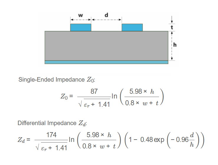
Single-Ended Impedance \( Z_0 \):
\[
Z_0 = \frac{87}{\sqrt{\varepsilon_r + 1.41}} \ln\left( \frac{5.98 \times h}{0.8 \times w + t} \right)
\]
Differential Impedance \( Z_d \):
\[
Z_d = \frac{174}{\sqrt{\varepsilon_r + 1.41}} \ln\left( \frac{5.98 \times h}{0.8 \times w + t} \right) \left( 1 - 0.48 \exp\left( -0.96 \frac{d}{h} \right) \right)
\]
Where:
- \( Z_0 \): Single-ended impedance in ohms
- \( Z_d \): Differential impedance in ohms
- \( \varepsilon_r \): Dielectric constant of the substrate
- \( h \): Substrate height (distance to ground plane)
- \( w \): Width of each trace
- \( t \): Thickness of each trace
- \( d \): Distance between the two traces
Unit Conversions:
- Input Dimensions (\( h, w, t, d \)):
- 1 mm = 39.3701 mils
- 1 μm = 0.0393701 mils
- Output Impedances (\( Z_0, Z_d \)):
- 1 ohm = 1000 mΩ
Steps:
- Enter the dielectric constant \( \varepsilon_r \).
- Enter the substrate height \( h \), trace width \( w \), trace thickness \( t \), and distance between traces \( d \), selecting the unit for each (mils, mm, or μm).
- Click "Calculate" to compute \( Z_0 \) and \( Z_d \).
- The results are initially displayed in ohms.
- Select a different unit for each impedance (ohms or mΩ) from the dropdowns after each result to convert the displayed values.
3. Importance of Differential Microstrip Impedance Calculation
Calculating the impedances of a differential microstrip is crucial for:
- Signal Integrity: Ensures minimal distortion and crosstalk in high-speed digital and RF signals.
- Impedance Matching: Reduces reflections by matching the transmission line impedance to the source and load.
- Design Optimization: Helps PCB designers select appropriate trace geometries for controlled impedance lines.
4. Using the Calculator
Examples:
- Example 1: \( \varepsilon_r = 4.5 \), \( h = 30 \) mils, \( w = 10 \) mils, \( t = 1.4 \) mils, \( d = 20 \) mils, Results in ohms
- Denominator: \( \sqrt{4.5 + 1.41} \approx 2.43 \)
- Ratio: \( \frac{5.98 \times 30}{0.8 \times 10 + 1.4} \approx 19.29 \)
- \( \ln(19.29) \approx 2.96 \)
- \( Z_0 = \frac{87}{2.43} \times 2.96 \approx 105.94 \, \text{ohms} \)
- Exp term: \( \exp\left(-0.96 \times \frac{20}{30}\right) \approx 0.53 \)
- \( Z_d = \frac{174}{2.43} \times 2.96 \times (1 - 0.48 \times 0.53) \approx 155.97 \, \text{ohms} \)
- Example 2: \( \varepsilon_r = 3.9 \), \( h = 0.762 \) mm, \( w = 254 \) μm, \( t = 0.0356 \) mm, \( d = 508 \) μm, Results in mΩ
- Convert to mils: \( h = 0.762 \times 39.3701 \approx 30 \), \( w = 254 \times 0.0393701 \approx 10 \), \( t = 0.0356 \times 39.3701 \approx 1.4 \), \( d = 508 \times 0.0393701 \approx 20 \)
- Denominator: \( \sqrt{3.9 + 1.41} \approx 2.31 \)
- Ratio and ln term same as above: \( \ln(19.29) \approx 2.96 \)
- \( Z_0 = \frac{87}{2.31} \times 2.96 \approx 111.46 \, \text{ohms} \)
- Exp term same as above: \( \approx 0.53 \)
- \( Z_d = \frac{174}{2.31} \times 2.96 \times (1 - 0.48 \times 0.53) \approx 164.04 \, \text{ohms} \)
- Results in mΩ: \( Z_0 = 111460 \, \text{mΩ} \), \( Z_d = 164040 \, \text{mΩ} \)
- Example 3: \( \varepsilon_r = 4.2 \), \( h = 762 \) μm, \( w = 10 \) mils, \( t = 1.4 \) mils, \( d = 0.508 \) mm, \( Z_0 \) in ohms, \( Z_d \) in mΩ
- Convert to mils: \( h = 762 \times 0.0393701 \approx 30 \), \( w = 10 \), \( t = 1.4 \), \( d = 0.508 \times 39.3701 \approx 20 \)
- Denominator: \( \sqrt{4.2 + 1.41} \approx 2.37 \)
- Ratio and ln term same as above: \( \ln(19.29) \approx 2.96 \)
- \( Z_0 = \frac{87}{2.37} \times 2.96 \approx 108.67 \, \text{ohms} \)
- Exp term same as above: \( \approx 0.53 \)
- \( Z_d = \frac{174}{2.37} \times 2.96 \times (1 - 0.48 \times 0.53) \approx 159.97 \, \text{ohms} \)
- Results: \( Z_0 = 108.67 \, \text{ohms} \), \( Z_d = 159970 \, \text{mΩ} \)
5. Frequently Asked Questions (FAQ)
Q: What is a differential microstrip?
A: A differential microstrip is a pair of parallel conductive traces on a dielectric substrate over a ground plane, used to transmit differential signals in high-speed digital and RF circuits.
Q: Why calculate both \( Z_0 \) and \( Z_d \)?
A: \( Z_0 \) (single-ended impedance) is useful for understanding the behavior of each trace individually, while \( Z_d \) (differential impedance) accounts for the coupling between the traces, which is critical for differential signaling.
Q: What factors affect the accuracy of these calculations?
A: The formulas assume ideal conditions. Real-world factors like frequency-dependent dielectric constants, copper roughness, and etch variations can affect accuracy. For precise designs, use field solvers or consult PCB manufacturers.
Differential Microstrip Impedance Calculator© - All Rights Reserved 2025
 Home
Home
 Back
Back