Home Back

Circular Waveguide Calculator

Circular Waveguide Formula

1. What is the Circular Waveguide Calculator?

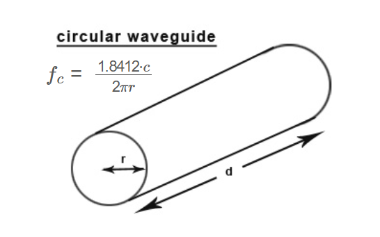
Definition: This calculator computes the cutoff frequency (\( f_c \)) of a circular waveguide for the dominant TE11 mode, given the waveguide's radius. The cutoff frequency is the lowest frequency at which the waveguide can propagate a signal in the specified mode.

Purpose: It assists RF engineers, technicians, and students in designing circular waveguides for microwave applications, such as antennas, radar systems, and communication devices.

2. How Does the Calculator Work?

The calculator uses the formula:

\( f_c = \frac{1.8412 \cdot c}{2 \pi r} \)

Where:

  • \( f_c \): Cutoff frequency (Hz)
  • \( c \): Speed of light in vacuum (\( 299,792,458 \, \text{m/s} \))
  • \( r \): Radius of the waveguide (m)
  • 1.8412: The first root of the derivative of the Bessel function for the TE11 mode (\( p'_{11} \))

Steps:

  • Enter the waveguide radius (\( r \)) and its unit (cm, m, mm, in, ft).
  • Select the output frequency unit (Hz, kHz, MHz, GHz).
  • Convert the radius to meters.
  • Compute the cutoff frequency in Hz using the formula.
  • Convert the frequency to the selected unit.
  • Display the result, formatted in scientific notation if the value is less than 0.001 or greater than 10000, otherwise with 4 decimal places.

3. Importance of Cutoff Frequency Calculation

Calculating the cutoff frequency of a circular waveguide is essential for:

  • Waveguide Design: Ensuring the waveguide operates above the cutoff frequency for the desired mode.
  • Frequency Selection: Selecting appropriate operating frequencies for microwave systems.
  • Signal Propagation: Preventing signal attenuation by operating above the cutoff frequency.
  • RF Applications: Optimizing performance in antennas, radar, and communication systems.

4. Using the Calculator

Example 1: Calculate the cutoff frequency for a typical waveguide:

  • Radius: \( r = 1 \, \text{cm} \)
  • Output Unit: GHz
  • Calculation:
    • Convert to meters: \( r = 0.01 \, \text{m} \)
    • Denominator: \( 2 \pi \times 0.01 \approx 0.0628319 \)
    • \( f_c = \frac{1.8412 \times 299,792,458}{0.0628319} \approx 8.785 \times 10^9 \, \text{Hz} \)
    • Convert to GHz: \( 8.785 \times 10^9 / 10^9 = 8.785 \, \text{GHz} \)
  • Result: Cutoff Frequency (f_c, TE11 Mode) = 8.7850 GHz

Example 2: Calculate for a smaller waveguide:

  • Radius: \( r = 5 \, \text{mm} \)
  • Output Unit: GHz
  • Calculation:
    • Convert to meters: \( r = 0.005 \, \text{m} \)
    • Denominator: \( 2 \pi \times 0.005 \approx 0.0314159 \)
    • \( f_c = \frac{1.8412 \times 299,792,458}{0.0314159} \approx 1.757 \times 10^{10} \, \text{Hz} \)
    • Convert to GHz: \( 1.757 \times 10^{10} / 10^9 = 17.57 \, \text{GHz} \)
  • Result: Cutoff Frequency (f_c, TE11 Mode) = 17.5700 GHz

5. Frequently Asked Questions (FAQ)

Q: Why is the radius restricted to positive values?
A: The radius must be greater than zero to be physically meaningful and to avoid division by zero in the formula.

Q: Why does this calculator only compute the TE11 mode?
A: The TE11 mode is the dominant mode for circular waveguides and is most commonly used. Other modes require different Bessel function roots, which can be added if needed.

Q: What happens if the waveguide is filled with a dielectric material?
A: This simplified calculator assumes an air-filled waveguide (\( \varepsilon_r = 1 \), \( \mu_r = 1 \)). For dielectric-filled waveguides, the cutoff frequency would be lower due to the material properties.

Q: Why is the result formatted in scientific notation?
A: Values less than 0.001 or greater than 10000 are displayed in scientific notation for readability.

Circular Waveguide Calculator© - All Rights Reserved 2025