1. What is a Balanced Attenuator Calculator?
Definition: This calculator determines the resistor value \( R1 \) for a balanced attenuator circuit (e.g., H or Pi configuration) based on the desired attenuation and the characteristic impedance \( Z_0 \).
Purpose: It helps engineers and RF designers select appropriate resistor values for attenuator circuits used in RF and microwave applications to control signal levels while maintaining impedance matching.
2. How Does the Calculator Work?
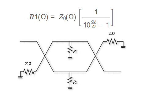
The calculator uses the following formula to compute \( R1 \):
\[
R1(\Omega) = Z_0(\Omega) \left[ \frac{1}{10^{\frac{\text{dB}}{20}} - 1} \right]
\]
Where:
- \( R1 \): Resistor value in ohms for the balanced attenuator circuit
- \( Z_0 \): Characteristic impedance in ohms (e.g., 50 ohms for typical RF systems)
- dB: Attenuation in decibels
Unit Conversions:
- Attenuation:
- 1 Np = 8.686 dB
- Impedance and \( R1 \):
- 1 kΩ = 1000 Ω
- 1 mΩ = 0.001 Ω
Steps:
- Enter the desired attenuation and select the unit (dB or Np).
- Enter the characteristic impedance \( Z_0 \) and select the unit (ohms, kΩ, or mΩ).
- Click "Calculate" to compute \( R1 \).
- The result \( R1 \) is initially displayed in ohms.
- Select a different unit for \( R1 \) (ohms, kΩ, or mΩ) from the dropdown after the result to convert the displayed value.
3. Importance of Balanced Attenuator Calculation
Calculating resistor values for a balanced attenuator is essential for:
- Signal Control: Attenuators reduce signal amplitude without distorting the waveform, critical in RF systems.
- Impedance Matching: Ensures minimal signal reflection in high-frequency circuits.
- Design Efficiency: Helps engineers select standard resistor values for practical implementation.
4. Using the Calculator
Examples:
- Example 1: Attenuation = 10 dB, \( Z_0 \) = 50 ohms, Result in ohms
- Calculate: \( 10^{\frac{10}{20}} = 10^{0.5} \approx 3.162 \)
- Denominator: \( 3.162 - 1 = 2.162 \)
- \( R1 = 50 \times \frac{1}{2.162} \approx 23.13 \, \text{ohms} \)
- Example 2: Attenuation = 0.691 Np, \( Z_0 \) = 0.075 kΩ, Result in mΩ
- Convert: Attenuation = \( 0.691 \times 8.686 \approx 6 \, \text{dB} \), \( Z_0 = 0.075 \times 1000 = 75 \, \text{ohms} \)
- Calculate: \( 10^{\frac{6}{20}} = 10^{0.3} \approx 1.995 \)
- Denominator: \( 1.995 - 1 = 0.995 \)
- \( R1 = 75 \times \frac{1}{0.995} \approx 75.38 \, \text{ohms} \)
- Result in mΩ: \( 75.38 \times 1000 = 75380 \, \text{mΩ} \)
- Example 3: Attenuation = 3 dB, \( Z_0 \) = 60000 mΩ, Result in kΩ
- Convert: \( Z_0 = 60000 \times 0.001 = 60 \, \text{ohms} \)
- Calculate: \( 10^{\frac{3}{20}} = 10^{0.15} \approx 1.4125 \)
- Denominator: \( 1.4125 - 1 = 0.4125 \)
- \( R1 = 60 \times \frac{1}{0.4125} \approx 145.45 \, \text{ohms} \)
- Result in kΩ: \( 145.45 \div 1000 = 0.1455 \, \text{kΩ} \)
5. Frequently Asked Questions (FAQ)
Q: What is a balanced attenuator?
A: A balanced attenuator is a circuit (e.g., H or Pi configuration) used in RF systems to reduce signal power while maintaining impedance matching on both input and output sides.
Q: Can this calculator be used for unbalanced attenuators?
A: No, this calculator is specific to balanced attenuators. Unbalanced attenuators (e.g., L or T configurations) require different formulas.
Q: What if the calculated \( R1 \) value is not a standard resistor value?
A: In practice, select the closest standard resistor value (e.g., E12 or E24 series) or use a combination of resistors to approximate the calculated value.
Balanced Attenuator Calculator© - All Rights Reserved 2025
 Home
Home
 Back
Back