1. What is a Valve and Fitting Head Loss Calculator?
Definition: This calculator computes the head loss (\( h_f \)) due to valves and fittings in a pipe system, expressed as the equivalent height of fluid column, using a loss coefficient \( K \).
Purpose: It is used in fluid dynamics and HVAC design to quantify energy losses caused by fittings, aiding in pipe system design and pump selection.
2. How Does the Calculator Work?
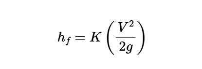
The calculator uses the following formula for head loss:
Head Loss:
\[
h_f = K \left( \frac{V^2}{2 g} \right)
\]
Where:
- \( h_f \): Head loss (ft, m)
- \( K \): Loss coefficient (dimensionless)
- \( V \): Average velocity (fps, m/s)
- \( g \): Acceleration of gravity (ft/sec², m/s²)
Unit Conversions:
- Velocity (\( V \)): fps, m/s (1 m/s = 3.28084 fps)
- Acceleration of Gravity (\( g \)): ft/sec², m/s² (1 m/s² = 3.28084 ft/sec²)
- Head Loss (\( h_f \)): ft, m (1 ft = 0.3048 m)
Steps:
- Enter the loss coefficient (\( K \)), average velocity (\( V \)), and acceleration of gravity (\( g \)), and select their units.
- Convert \( V \) and \( g \) to fps and ft/sec², respectively.
- Calculate the head loss using the formula.
- Convert the result to the selected unit (ft or m).
- Display the result with 5 decimal places, or in scientific notation if the value is greater than 10,000 or less than 0.00001.
3. Importance of Valve and Fitting Head Loss Calculation
Calculating head loss due to valves and fittings is crucial for:
- Pipe System Design: Accounts for additional energy losses to ensure proper pipe sizing and pump requirements.
- Energy Efficiency: Minimizes energy consumption by optimizing system components to reduce losses.
- System Performance: Ensures adequate fluid flow for industrial, HVAC, or plumbing applications.
4. Using the Calculator
Examples:
- Example 1: For \( K = 1.5 \), \( V = 4 \, \text{fps} \), \( g = 32.2 \, \text{ft/sec²} \), head loss in ft:
- \( h_f = 1.5 \times \left( \frac{4^2}{2 \times 32.2} \right) \approx 1.5 \times \frac{16}{64.4} \approx 0.373 \)
- Since 0.373 < 10000 and > 0.00001, display with 5 decimal places: \( 0.37300 \)
- Example 2: For \( K = 2.0 \), \( V = 1.2 \, \text{m/s} \), \( g = 9.81 \, \text{m/s²} \), head loss in m:
- Convert: \( V = 1.2 \times 3.28084 \approx 3.93701 \, \text{fps} \)
- \( g = 9.81 \times 3.28084 \approx 32.1850 \, \text{ft/sec²} \)
- \( h_f = 2.0 \times \left( \frac{3.93701^2}{2 \times 32.1850} \right) \approx 2.0 \times \frac{15.500}{64.37} \approx 0.482 \)
- Convert to m: \( 0.482 \times 0.3048 \approx 0.147 \)
- Since 0.147 < 10000 and > 0.00001, display with 5 decimal places: \( 0.14700 \)
- Example 3: For \( K = 0.8 \), \( V = 5 \, \text{fps} \), \( g = 32.2 \, \text{ft/sec²} \), head loss in ft:
- \( h_f = 0.8 \times \left( \frac{5^2}{2 \times 32.2} \right) \approx 0.8 \times \frac{25}{64.4} \approx 0.311 \)
- Since 0.311 < 10000 and > 0.00001, display with 5 decimal places: \( 0.31100 \)
5. Frequently Asked Questions (FAQ)
Q: What does valve and fitting head loss represent?
A: Head loss (\( h_f \)) quantifies the energy loss due to flow through valves and fittings, expressed as the equivalent height of fluid column, impacting system efficiency.
Q: How can I determine the input parameters?
A: The loss coefficient (\( K \)) is obtained from tables based on the type and size of the valve or fitting (e.g., 1.5 for a typical elbow). Average velocity (\( V \)) is calculated from flow rate and pipe area. Acceleration of gravity (\( g \)) is typically 32.2 ft/sec² in US units or 9.81 m/s² in SI units.
Q: Why is valve and fitting head loss important in pipe system design?
A: It ensures accurate accounting of energy losses for proper pump sizing and system performance optimization.
Valve and Fitting Head Loss Calculator© - All Rights Reserved 2025
 Home
Home
 Back
Back