1. What is a Total Pressure Loss in Duct Section Calculator?
Definition: This calculator computes the total pressure loss (\( \Delta P \)) in a duct section, combining friction losses and dynamic losses from fittings in HVAC systems.
Purpose: It is used in HVAC design to quantify the pressure drop in a duct section, aiding in fan selection, duct sizing, and system efficiency.
2. How Does the Calculator Work?
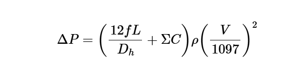
The calculator uses the following formula for total pressure loss:
Total Pressure Loss:
\[
\Delta P = \left( \frac{12 f L}{D_h} + \Sigma C \right) \rho \left( \frac{V}{1097} \right)^2
\]
Where:
- \( \Delta P \): Total pressure loss (in. of water, Pa)
- \( f \): Friction factor (dimensionless)
- \( L \): Duct length (ft, m)
- \( D_h \): Hydraulic diameter (in., m)
- \( \Sigma C \): Sum of local loss coefficients within the duct section (dimensionless)
- \( \rho \): Air density (lb_f/ft³, kg/m³)
- \( V \): Velocity of air (fpm, m/s)
Unit Conversions:
- Duct Length (\( L \)): ft, m (1 m = 3.28084 ft)
- Hydraulic Diameter (\( D_h \)): in., m (1 m = 39.3701 in.)
- Air Density (\( \rho \)): lb_f/ft³, kg/m³ (1 kg/m³ = 0.062428 lb_f/ft³)
- Velocity (\( V \)): fpm, m/s (1 m/s = 196.850 fpm)
- Total Pressure Loss (\( \Delta P \)): in. of water, Pa (1 in. of water = 248.84 Pa)
Steps:
- Enter the friction factor (\( f \)), duct length (\( L \)), hydraulic diameter (\( D_h \)), sum of local loss coefficients (\( \Sigma C \)), air density (\( \rho \)), and air velocity (\( V \)), and select their units.
- Convert \( L \), \( D_h \), \( \rho \), and \( V \) to ft, in., lb_f/ft³, and fpm, respectively.
- Calculate the total pressure loss using the formula.
- Convert the result to the selected unit (in. of water or Pa).
- Display the result with 5 decimal places, or in scientific notation if the value is greater than 10,000 or less than 0.00001.
3. Importance of Total Pressure Loss Calculation
Calculating the total pressure loss in a duct section is crucial for:
- HVAC System Design: Determines the combined pressure drop from friction and fittings, guiding fan and duct sizing.
- Energy Efficiency: Optimizes duct design to minimize pressure losses, reducing energy consumption.
- System Performance: Ensures adequate air flow for ventilation and thermal comfort.
4. Using the Calculator
Examples:
- Example 1: For \( f = 0.01106 \), \( L = 40 \, \text{ft} \), \( D_h = 28.8 \, \text{in.} \), \( \Sigma C = 0.32 \), \( \rho = 0.075 \, \text{lb_f/ft³} \), \( V = 600 \, \text{fpm} \), total pressure loss in in. of water:
- \( \frac{12 \times 0.01106 \times 40}{28.8} \approx 0.1844 \)
- \( \frac{600}{1097} \approx 0.54695 \), \( \left( \frac{600}{1097} \right)^2 \approx 0.29915 \)
- \( \Delta P = (0.1844 + 0.32) \times 0.075 \times 0.29915 \approx 0.5044 \times 0.022436 \approx 0.01132 \)
- Since 0.01132 < 10000 and > 0.00001, display with 5 decimal places: \( 0.01132 \)
- Example 2: For \( f = 0.02 \), \( L = 12 \, \text{m} \), \( D_h = 0.5 \, \text{m} \), \( \Sigma C = 0.5 \), \( \rho = 1.2 \, \text{kg/m³} \), \( V = 5 \, \text{m/s} \), total pressure loss in Pa:
- Convert: \( L = 12 \times 3.28084 \approx 39.37008 \, \text{ft} \)
- \( D_h = 0.5 \times 39.3701 \approx 19.68505 \, \text{in.} \)
- \( \rho = 1.2 \times 0.062428 \approx 0.074914 \, \text{lb_f/ft³} \)
- \( V = 5 \times 196.850 \approx 984.25 \, \text{fpm} \)
- \( \frac{12 \times 0.02 \times 39.37008}{19.68505} \approx 0.4800 \)
- \( \frac{984.25}{1097} \approx 0.89713 \), \( \left( \frac{984.25}{1097} \right)^2 \approx 0.80484 \)
- \( \Delta P = (0.4800 + 0.5) \times 0.074914 \times 0.80484 \approx 0.9800 \times 0.060297 \approx 0.059091 \, \text{in. of water} \)
- Convert to Pa: \( 0.059091 \times 248.84 \approx 14.705 \)
- Since 14.705 < 10000 and > 0.00001, display with 5 decimal places: \( 14.70500 \)
- Example 3: For \( f = 0.015 \), \( L = 50 \, \text{ft} \), \( D_h = 12 \, \text{in.} \), \( \Sigma C = 0.4 \), \( \rho = 0.08 \, \text{lb_f/ft³} \), \( V = 800 \, \text{fpm} \), total pressure loss in in. of water:
- \( \frac{12 \times 0.015 \times 50}{12} = 0.75 \)
- \( \frac{800}{1097} \approx 0.72926 \), \( \left( \frac{800}{1097} \right)^2 \approx 0.53182 \)
- \( \Delta P = (0.75 + 0.4) \times 0.08 \times 0.53182 \approx 1.15 \times 0.042546 \approx 0.048928 \)
- Since 0.048928 < 10000 and > 0.00001, display with 5 decimal places: \( 0.04893 \)
5. Frequently Asked Questions (FAQ)
Q: What does the total pressure loss in a duct section represent?
A: The total pressure loss (\( \Delta P \)) quantifies the combined pressure drop due to friction and fittings in a duct section, affecting HVAC system performance.
Q: How can I determine the input parameters?
A: The friction factor (\( f \)) is calculated (e.g., using the Altshul-Tsal equation) or obtained from standards. Duct length (\( L \)) and hydraulic diameter (\( D_h \)) are measured. The sum of local loss coefficients (\( \Sigma C \)) comes from fitting loss tables. Air density (\( \rho \)) is derived from conditions, and velocity (\( V \)) is measured or calculated.
Q: Why is total pressure loss important in HVAC design?
A: It ensures accurate fan sizing and duct design to maintain air flow, improving energy efficiency and system performance.
Total Pressure Loss in Duct Section Calculator© - All Rights Reserved 2025
 Home
Home
 Back
Back