1. What is a Friction Factor Calculator for Turbulent Flow, Rough Pipes?
Definition: This calculator computes the friction factor (\( f \)) for turbulent flow in rough pipes, using either the Fully Rough Region formula or the Colebrook Equation based on flow conditions.
Purpose: It is used in HVAC systems to determine the friction factor for calculating pressure losses in ducts, essential for efficient system design.
2. How Does the Calculator Work?
The calculator uses the following formulas for turbulent flow in rough pipes:
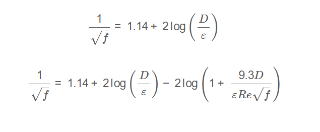
Fully Rough Region (when \( Re \sqrt{f} \cdot \frac{\varepsilon}{D} > 200 \)):
\[
\frac{1}{\sqrt{f}} = 1.14 + 2 \log \left( \frac{D}{\varepsilon} \right)
\]
Colebrook Equation (otherwise):
\[
\frac{1}{\sqrt{f}} = 1.14 + 2 \log \left( \frac{D}{\varepsilon} \right) - 2 \log \left( 1 + \frac{9.3 D}{\varepsilon Re \sqrt{f}} \right)
\]
Where:
- \( f \): Friction factor (dimensionless)
- \( D \): Pipe diameter (ft, in, m)
- \( \varepsilon \): Surface roughness height (ft, in, m)
- \( Re \): Reynolds number (dimensionless, user input)
Unit Conversions:
- Diameter (\( D \)) and Roughness Height (\( \varepsilon \)): ft, in (1 in = \( \frac{1}{12} \) ft), m (1 m = 3.28084 ft)
Steps:
- Enter the Reynolds number (\( Re \)), pipe diameter (\( D \)), and roughness height (\( \varepsilon \)).
- Convert \( D \) and \( \varepsilon \) to base units (ft).
- Validate that \( Re > 2300 \) (turbulent flow requirement).
- Compute an initial guess for \( f \) using the Fully Rough Region formula.
- Check the criterion \( Re \sqrt{f} \cdot \frac{\varepsilon}{D} \):
- If \( > 200 \), use the Fully Rough Region formula.
- Otherwise, solve the Colebrook Equation iteratively using the Newton-Raphson method.
- Display the result, using scientific notation for values less than 0.001, otherwise with 4 decimal places.
3. Importance of Friction Factor Calculation
Calculating the friction factor for turbulent flow in rough pipes is crucial for:
- HVAC Design: Enables accurate pressure drop calculations using the Darcy-Weisbach equation, ensuring proper duct sizing.
- Energy Efficiency: Helps minimize energy losses by accounting for pipe roughness in duct design.
- System Performance: Ensures consistent airflow and pressure distribution in HVAC systems.
4. Using the Calculator
Examples:
- Example 1 (Fully Rough Region): For \( Re = 5000000 \), \( D = 0.5 \, \text{ft} \), \( \varepsilon = 0.001 \, \text{ft} \):
- Initial Guess: \( \frac{D}{\varepsilon} = \frac{0.5}{0.001} = 500 \), \( \frac{1}{\sqrt{f}} = 1.14 + 2 \log_{10}(500) \approx 6.54 \), \( f \approx 0.0234 \)
- Criterion: \( \frac{\varepsilon}{D} = 0.002 \), \( Re \sqrt{f} \cdot \frac{\varepsilon}{D} \approx 5000000 \times \sqrt{0.0234} \times 0.002 \approx 1530 > 200 \)
- Method: Fully Rough Region Formula
- Friction Factor: \( f \approx 0.0234 \)
- Example 2 (Colebrook Equation): For \( Re = 5000 \), \( D = 0.5 \, \text{ft} \), \( \varepsilon = 0.0001 \, \text{ft} \):
- Initial Guess: \( \frac{D}{\varepsilon} = \frac{0.5}{0.0001} = 5000 \), \( \frac{1}{\sqrt{f}} = 1.14 + 2 \log_{10}(5000) \approx 8.94 \), \( f \approx 0.0125 \)
- Criterion: \( \frac{\varepsilon}{D} = 0.0002 \), \( Re \sqrt{f} \cdot \frac{\varepsilon}{D} \approx 5000 \times \sqrt{0.0125} \times 0.0002 \approx 0.112 < 200 \)
- Method: Colebrook Equation (Iterative Solution)
- After iteration: \( f \approx 0.0328 \)
5. Frequently Asked Questions (FAQ)
Q: What is the friction factor in turbulent flow for rough pipes?
A: The friction factor (\( f \)) is a dimensionless quantity used to calculate pressure losses in turbulent flow through rough pipes, determined using either the Fully Rough Region formula or the Colebrook Equation.
Q: Why is the friction factor important in HVAC systems?
A: It is essential for calculating pressure drops in ducts, ensuring efficient design and operation of HVAC systems in turbulent flow conditions.
Q: When is the Fully Rough Region formula used?
A: The Fully Rough Region formula is used when \( Re \sqrt{f} \cdot \frac{\varepsilon}{D} > 200 \), indicating that the friction factor is independent of the Reynolds number and depends only on the relative roughness.
Friction Factor Calculator for Turbulent Flow, Rough Pipes© - All Rights Reserved 2025
 Home
Home
 Back
Back