1. What is the Simply-Supported Beam Deflection Calculator?
Definition: This calculator estimates the maximum deflection of a simply-supported beam under various load conditions, based on load, beam properties, and geometry.
Purpose: It assists engineers, architects, and designers in analyzing beam behavior to ensure structural integrity and compliance with design specifications.
2. How Does the Calculator Work?
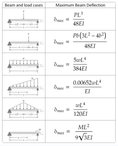
The calculator applies specific deflection formulas for simply-supported beams, as shown in the referenced table. The general form is:
- \[ \delta_{\text{max}} = \frac{\text{Load Term} \times \text{Length Term}}{E \times I} \]
Where:
- \( \delta_{\text{max}} \): Maximum deflection (mm, cm, m, in, or ft);
- \( P \): Point load (N or lbf);
- \( w \): Distributed load (N/m or lbf/ft);
- \( M \): Moment (N·m or lbf·ft);
- \( L \): Beam length (mm, cm, m, in, or ft);
- \( a, b \): Distances from supports (mm, cm, m, in, or ft);
- \( E \): Modulus of elasticity (Pa or psi);
- \( I \): Moment of inertia (mm⁴, cm⁴, m⁴, in⁴, or ft⁴).
Steps:
- Select the load case (e.g., Central Point Load).
- Enter the load parameters (e.g., \( P \), \( w \), \( M \), \( a \)) and their units.
- Enter the beam length (\( L \)), modulus of elasticity (\( E \)), and moment of inertia (\( I \)), selecting appropriate units.
- Convert all inputs to SI units (N, N/m, N·m, m, Pa, m⁴).
- Apply the corresponding deflection formula.
- Convert the deflection to the selected output unit (mm, cm, m, in, or ft).
- Display the result, formatted in scientific notation if the absolute value is less than 0.001, otherwise with 4 decimal places.
3. Importance of Beam Deflection Calculation
Calculating beam deflection is crucial for:
- Structural Safety: Ensures deflections remain within acceptable limits to prevent failure.
- Design Compliance: Verifies beams meet building codes and performance standards.
- Material Selection: Helps choose appropriate materials and cross-sections based on modulus and inertia.
- Functionality: Prevents excessive deformation that could affect aesthetics or functionality.
4. Using the Calculator
Example 1 (Central Point Load): Calculate the deflection for a simply-supported beam with a central point load:
- Load Case: Central Point Load;
- Point Load: \( P = 5000 \, \text{N} \);
- Beam Length: \( L = 3 \, \text{m} \);
- Modulus of Elasticity: \( E = 200 \times 10^9 \, \text{Pa} \);
- Moment of Inertia: \( I = 1 \times 10^8 \, \text{mm}^4 = 1 \times 10^{-4} \, \text{m}^4 \);
- Output Unit: Millimeters;
- Deflection: \( \delta_{\text{max}} = \frac{5000 \times 3^3}{48 \times 200 \times 10^9 \times 1 \times 10^{-4}} = 0.00140625 \, \text{m} = 1.40625 \, \text{mm} \);
- Result: \( \delta_{\text{max}} = 1.4063 \, \text{mm} \).
Example 2 (Uniform Distributed Load): Calculate the deflection with a uniform distributed load:
- Load Case: Uniform Distributed Load;
- Distributed Load: \( w = 1000 \, \text{lbf/ft} \approx 14593.9 \, \text{N/m} \);
- Beam Length: \( L = 10 \, \text{ft} \approx 3.048 \, \text{m} \);
- Modulus of Elasticity: \( E = 29 \times 10^6 \, \text{psi} \approx 200 \times 10^9 \, \text{Pa} \);
- Moment of Inertia: \( I = 100 \, \text{in}^4 \approx 4.16231 \times 10^{-5} \, \text{m}^4 \);
- Output Unit: Inches;
- Deflection: \( \delta_{\text{max}} = \frac{5 \times 14593.9 \times 3.048^4}{384 \times 200 \times 10^9 \times 4.16231 \times 10^{-5}} \approx 0.019717 \, \text{m} \approx 0.77626 \, \text{in} \);
- Result: \( \delta_{\text{max}} = 0.7763 \, \text{in} \).
5. Frequently Asked Questions (FAQ)
Q: What is the modulus of elasticity?
A: The modulus of elasticity (\( E \)) measures a material’s stiffness, typically in Pascals (Pa) or psi. Common values include 200 GPa for steel and 70 GPa for aluminum.
Q: How do I find the moment of inertia?
A: The moment of inertia (\( I \)) depends on the beam’s cross-sectional shape (e.g., \( I = \frac{b h^3}{12} \) for a rectangular section). Use standard formulas or structural tables.
Q: Why does the point load at any point use \( b = \min(a, L-a) \)?
A: The formula uses the smaller distance from either support (\( b \)) to maximize deflection, ensuring symmetry in calculations.
Simply-Supported Beam Deflection Calculator© - All Rights Reserved 2025
 Home
Home
 Back
Back